Page 350 of 525

•The capabilities of a BAS-equipped vehicle must
never be exploited in a reckless or dangerous
manner which could jeopardize the user ’s safety or
the safety of others.
Electro")
WARNING!(Continued)
•The capabilities of a BAS-equipped vehicle must
never be exploited in a reckless or dangerous
manner which could jeopardize the user ’s safety or
the safety of others.
Electronic Roll Mitigation (ERM)
This system anticipates the potential for wheel lift by
monitoring the driver ’s steering wheel input and the
speed of the vehicle. When ERM determines that the rate
of change of the steering wheel angle and vehicles speed
are sufficient to potentially cause wheel lift, it applies the
brake of the appropriate wheel and may also reduce
engine power to lessen the chance that wheel lift will
occur. ERM will only intervene during very severe or
evasive driving maneuvers.
ERM can only reduce the chance of wheel lift occurring
during severe or evasive driving maneuvers. It can not prevent wheel lift due to other factors such as road
conditions, leaving the roadway or striking objects or
other vehicles.
NOTE:
Anytime the ESC system is in the “Full Off”
mode, ERM is disabled. Refer to “Electronic Stability
Control (ESC)” in this section for a complete explanation
of the available ESC modes.WARNING!
Many factors, such as vehicle loading, road condi-
tions and driving conditions, influence the chance
that wheel lift or rollover may occur. ERM cannot
prevent all wheel lift or roll overs, especially those
that involve leaving the roadway or striking objects
or other vehicles. The capabilities of an ERM-
equipped vehicle must never be exploited in a reck-
less or dangerous manner which could jeopardize the
user’s safety or the safety of others.
348 STARTING AND OPERATING
Page 352 of 525

WARNING!
HDC is only intended to assist the driver in control-
ling vehicle speed when descending hills. The driver
must remain attentive to the driving conditions and
is responsible for maintaining a safe vehicle speed.
Hill Start Assist (HSA) – Manual Transmission
Only
The HSA system is designed to assist the driver when
starting a vehicle from a stop on a hill. HSA will maintain
the level of brake pressure the driver applied for a short
period of time after the driver takes their foot off of the
brake pedal. If the driver does not apply the throttle
during this short period of time, the system will release
brake pressure and the vehicle will roll down the hill. The
system will release brake pressure in proportion to
amount of throttle applied as the vehicle starts to move in
the intended direction of travel.
HSA Activation Criteria
The following criteria must be met in order for HSA to
activate:
•Vehicle must be stopped.
• Vehicle must be on a 7% grade or greater hill.
• Gear selection matches vehicle uphill direction (i.e.,
vehicle facing uphill is in forward gear; vehicle back-
ing uphill is in REVERSE gear).
WARNING!
There may be situations on minor hills (i.e., less than
8%), with a loaded vehicle, or while pulling a trailer,
when the system will not activate and slight rolling
may occur. This could cause a collision with another
vehicle or object. Always remember the driver is
responsible for braking the vehicle.
350 STARTING AND OPERATING
Page 357 of 525

NOTE:The “ESC OFF” message will display and an
audible chime will sound when the shift lever is placed
into the PARK position from any other position, and then
moved out of the PARK position. This will occur even if
the message was previously cleared.
WARNING!
With the ESC in the �Full Off�mode, the engine
torque reduction and stability features are disabled.
Therefore, the enhanced vehicle stability offered by
ESP is unavailable. In an emergency evasive maneu-
ver, the ESC system will not engage to assist in
maintaining stability. “ESC Off” mode is intended
for off-highway or off-road use only.
ESC Activation/Malfunction Indicator Light And
ESC OFF Indicator Light
The “ESC Activation/Malfunction Indicator
Light” in the instrument cluster will come on
when the ignition switch is turned to the ON
position. It should go out with the engine
running. If the “ESC Activation/Malfunction Indicator
Light” comes on continuously with the engine running, a
malfunction has been detected in the ESC system. If this
light remains on after several ignition cycles, and the
vehicle has been driven several miles (kilometers) at
speeds greater than 30 mph (48 km/h), see your autho-
rized dealer as soon as possible to have the problem
diagnosed and corrected.
5
STARTING AND OPERATING 355
Page 361 of 525
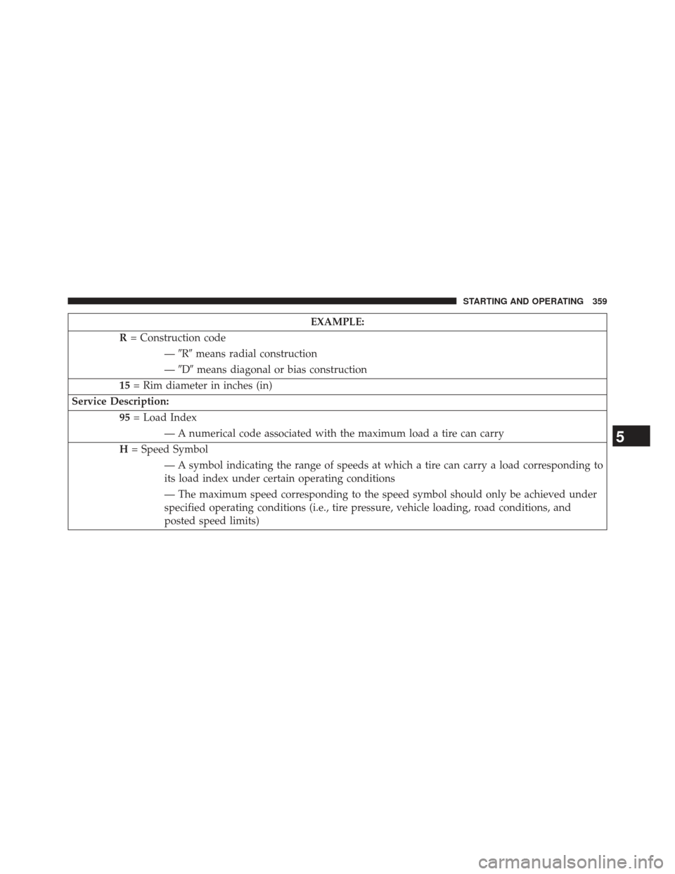
EXAMPLE:
R = Construction code
—�R� means radial construction
— �D� means diagonal or bias construction
15 = Rim diameter in inches (in)
Service Description: 95= Load Index
— A numerical code associated with the maximum load a tire can carry
H = Speed Symbol
— A symbol indicating the range of speeds at which a tire can carry a load corresponding to
its load index under certain operating conditions
— The maximum speed corresponding to the speed symbol should only be achieved under
specified operating conditions (i.e., tire pressure, vehicle loading, road conditions, and
posted speed limits)
5
STARTING AND OPERATING 359
Page 371 of 525

•Unequal tire pressures from one side of the vehicle
to the other can cause the vehicle to drift to the
right or left.
• Always drive with each tire inflated to the recom-
mend")
WARNING!(Continued)
•Unequal tire pressures from one side of the vehicle
to the other can cause the vehicle to drift to the
right or left.
• Always drive with each tire inflated to the recom-
mended cold tire inflation pressure.
Economy
Improper inflation pressures can cause uneven wear pat-
terns to develop across the tire tread. These abnormal wear
patterns will reduce tread life resulting in a need for earlier
tire replacement. Under-inflation also increases tire rolling
resistance resulting in higher fuel consumption.
Ride Comfort And Vehicle Stability
Proper tire inflation contributes to a comfortable ride.
Over-inflation produces a jarring and uncomfortable
ride. Both under-inflation and over-inflation affect the stability of the vehicle and can produce a feeling of
sluggish response or over responsiveness in the steering.
Unequal tire pressures can cause erratic and unpredict-
able steering response.
Unequal tire pressure from side to side may cause the
vehicle to drift left or right.
Tire Inflation Pressures
The proper cold tire inflation pressure is listed on the
driver’s side “B” Pillar or rear edge of the driver’s side
door.
The tire pressure should be checked and adjusted as well
as inspected for signs of tire wear or visible damage at
least once a month. Use a good quality pocket-type gauge
to check tire pressure. Do not make a visual judgement
when determining proper inflation. Radial tires may look
properly inflated even when they are under-inflated.5
STARTING AND OPERATING 369
Page 372 of 525

CAUTION!
After inspecting or adjusting the tire pressure, al-
ways reinstall the valve stem cap. This will prevent
moisture and dirt from entering the valve stem,
which could damage the valve stem.
Inflation pressures specified on the placard are always
“cold tire inflation pressure.” Cold tire inflation pressure
is defined as the tire pressure after the vehicle has not
been driven for at least three hours, or driven less than 1
mile (1.6 km) after a three hour period. The cold tire
inflation pressure must not exceed the maximum infla-
tion pressure molded into the tire sidewall.
Check tire pressures more often if subject to a wide range
of outdoor temperatures, as tire pressures vary with
temperature changes. Tire pressures change by approximately 1 psi (7 kPa) per
12°F (7°C) of air temperature change. Keep this in mind
when checking tire pressure inside a garage, especially in
the winter.
Example: If garage temperature = 68°F (20°C) and the
outside temperature = 32°F (0°C) then the cold tire
inflation pressure should be increased by 3 psi (21 kPa),
which equals 1 psi (7 kPa) for every 12°F (7°C) for this
outside temperature condition.
Tire pressure may increase from 2 to 6 psi (13 to 40 kPa)
during operation. DO NOT reduce this normal pressure
build up or your tire pressure will be too low.
370 STARTING AND OPERATING
Page 381 of 525
TIRE ROTATION RECOMMENDATIONS
The tires on the front and rear of your vehicle operate at
different loads and perform different steering, driving,
and braking functions. For these reasons, they wear at
unequal rates.
These effects can be reduced by timely rotation of tires.
The benefits of rotation are especially worthwhile with
aggressive tread designs such as those on all season type
tires. Rotation will increase tread life, help to maintain
mud, snow and wet traction levels, and contribute to a
smooth, quiet ride.
Refer to the “Maintenance Schedule” for the proper
maintenance intervals. The reasons for any rapid or
unusual wear should be corrected prior to rotation being
performed.The suggested rotation method is the “rearward cross”
shown in the following diagram. This rotation pattern
does not apply to some directional tires that must not be
reversed.
Tire Rotation
5
STARTING AND OPERATING 379
Page 384 of 525

NOTE:
•The TPMS is not intended to replace normal tire care
and maintenance or to provide warning of a tire failure
or condition.
• The TPMS should not be used as a tire pressure gauge
while adjusting your tire pressure.
• Driving on a significantly under-inflated tire causes
the tire to overheat and can lead to tire failure.
Under-inflation also reduces fuel efficiency and tire
tread life, and may affect the vehicle’s handling and
stopping ability.
• The TPMS is not a substitute for proper tire mainte-
nance, and it is the driver ’s responsibility to maintain
correct tire pressure using an accurate tire gauge, even
if under-inflation has not reached the level to trigger
illumination of the Tire Pressure Monitoring Telltale
Light. •
Seasonal temperature changes will affect tire pressure,
and the TPMS will monitor the actual tire pressure in
the tire.
Base System
This is the TPMS warning indicator located in the
instrument cluster.
The TPMS uses wireless technology with wheel rim
mounted electronic sensors to monitor tire pressure lev-
els. Sensors, mounted to each wheel as part of the valve
stem, transmit tire pressure readings to the Receiver
Module.
NOTE: It is particularly important for you to check the
tire pressure in all of the tires on your vehicle regularly
and to maintain the proper pressure.
The TPMS consists of the following components:
• Receiver Module
382 STARTING AND OPERATING