Page 339 of 525
soft bottoms, the vehicle will sink in, effectively increas-
ing the water level on the vehicle. Be sure to consider this
when determining the depth and the ability to safely
cross.
Crossing Puddles, Pools, Flooded Areas Or Other
Standing Water
Puddles, pools, flooded or other standing water areas
normally contain murky or muddy waters. These water
types normally contain hidden obstacles and make it
difficult to determine an accurate water depth, approach
angle, and bottom condition. Murky or muddy water
holes are where you want to hook up tow straps prior to
entering. This makes for a faster, cleaner and easier
vehicle recovery. If you are able to determine you can
safely cross, than proceed using the low and slow
method.
CAUTION!
Muddy waters can reduce the cooling system effec-
tiveness by depositing debris onto the radiator.
After Driving Off-Road
Off-road operation puts more stress on your vehicle than
does most on-road driving. After going off-road, it is
always a good idea to check for damage. That way you
can get any problems taken care of right away and have
your vehicle ready when you need it.
•Completely inspect the underbody of your vehicle.
Check tires, body structure, steering, suspension, and
exhaust system for damage.
• Inspect the radiator for mud and debris and clean as
required.
5
STARTING AND OPERATING 337
Page 346 of 525
Anti-Lock Brake System (ABS)
The ABS provides increased vehicle stability and brake
performance under most braking conditions. The system
automatically “pumps” the brakes during severe braking
conditions to prevent wheel lock-up.
WARNING!
•Pumping of the anti-lock brakes will diminish
their effectiveness and may lead to a collision.
Pumping makes the stopping distance longer. Just
press firmly on your brake pedal when you need to
slow down or stop.
• The ABS cannot prevent the natural laws of phys-
ics from acting on the vehicle, nor can it increase
braking or steering efficiency beyond that afforded
by the condition of the vehicle brakes and tires or
the traction afforded.
(Continued)
WARNING! (Continued)
•The ABS cannot prevent collisions, including those
resulting from excessive speed in turns, following
another vehicle too closely, or hydroplaning.
• The capabilities of an ABS-equipped vehicle must
never be exploited in a reckless or dangerous
manner which could jeopardize the user’s safety or
the safety of others.
The “ABS Warning Light” monitors the ABS
System. The light will come on when the
ignition switch is turned to the ON position
and may stay on for as long as four seconds.
If the “ABS Warning Light” remains on or comes on
while driving, it indicates that the anti-lock portion of the
brake system is not functioning and that service is
344 STARTING AND OPERATING
Page 348 of 525
WARNING!
The Anti-Lock Brake System (ABS) contains sophis-
ticated electronic equipment that may be susceptible
to interference caused by improperly installed or
high output radio transmitting equipment. This in-
terference can cause possible loss of Anti-Lock brak-
ing capability. Installation of such equipment should
be performed by qualified professionals.
All vehicle wheels and tires must be the same size and
type and tires must be properly inflated to produce
accurate signals for the computer.
ELECTRONIC BRAKE CONTROL SYSTEM
Your vehicle may be equipped with an optional ad-
vanced electronic brake control system that includes
Anti-Lock Brake System (ABS), Traction Control System (TCS), Brake Assist System (BAS), Electronic Roll Mitiga-
tion (ERM), Hill Descent Control (HDC), Hill Start Assist
(HSA), and Electronic Stability Control (ESC). All sys-
tems work together to enhance vehicle stability and
control in various driving conditions and are commonly
referred to as ESC.
Anti-Lock Brake System (ABS)
This system aids the driver in maintaining vehicle control
under adverse braking conditions. The system controls
hydraulic brake pressure to prevent wheel lockup and
help avoid skidding on slippery surfaces during braking.
Refer to “Anti-Lock Brake System” in “Starting and
Operating” for further information.
Traction Control System (TCS)
This system monitors the amount of wheel spin of each of
the driven wheels. If wheel spin is detected, brake
pressure is applied to the slipping wheel(s) and engine
power is reduced to provide enhanced acceleration and
346 STARTING AND OPERATING
Page 358 of 525

The “ESC Activation/Malfunction Indicator Light” (lo-
cated in the instrument cluster) starts to flash as soon as
the tires lose traction and the ESC system becomes active.
The “ESC Activation/Malfunction Indicator Light” also
flashes when TCS is active. If the “ESC Activation/
Malfunction Indicator Light” begins to flash during ac-
celeration, ease up on the accelerator and apply as little
throttle as possible. Be sure to adapt your speed and
driving to the prevailing road conditions.
NOTE:
•The “ESC Activation/Malfunction Indicator Light”
and the “ESC OFF Indicator Light” come on momen-
tarily each time the ignition switch is turned ON. •
Each time the ignition is turned ON, the ESC system
will be ON even if it was turned off previously.
• The ESC system will make buzzing or clicking sounds
when it is active. This is normal; the sounds will stop
when ESC becomes inactive following the maneuver
that caused the ESC activation.
The “ESC OFF Indicator Light” indicates the
Electronic Stability Control (ESC) is off.
356 STARTING AND OPERATING
Page 359 of 525
TIRE SAFETY INFORMATION
Tire MarkingsNOTE:
•P (Passenger) - Metric tire sizing is based on U.S.
design standards. P-Metric tires have the letter “P”
molded into the sidewall preceding the size designa-
tion. Example: P215/65R15 95H.
• European-Metric tire sizing is based on European
design standards. Tires designed to this standard have
the tire size molded into the sidewall beginning with
the section width. The letter �P�is absent from this tire
size designation. Example: 215/65R15 96H.
• LT (Light Truck) - Metric tire sizing is based on U.S.
design standards. The size designation for LT-Metric
tires is the same as for P-Metric tires except for the
letters “LT” that are molded into the sidewall preced-
ing the size designation. Example: LT235/85R16.
• Temporary spare tires are spares designed for tempo-
rary emergency use only. Temporary high pressure
1 — U.S. DOT Safety Standards
Code (TIN) 4 — Maximum Load
2 — Size Designation 5 — Maximum Pressure
3 — Service Description 6 — Treadwear, Traction and
Temperature Grades
5
STARTING AND OPERATING 357
Page 360 of 525
compact spare tires have the letter “T” or “S” molded
into the sidewall preceding the size designation.
Example: T145/80D18 103M.•
High flotation tire sizing is based on U.S. design
standards and it begins with the tire diameter molded
into the sidewall. Example: 31x10.5 R15 LT.
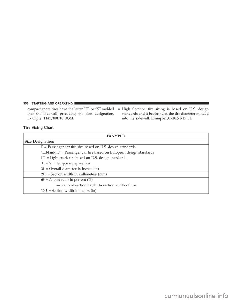
Tire Sizing Chart
EXAMPLE:
Size Designation: P= Passenger car tire size based on U.S. design standards
�....blank....� = Passenger car tire based on European design standards
LT = Light truck tire based on U.S. design standards
TorS= Temporary spare tire
31 = Overall diameter in inches (in)
215 = Section width in millimeters (mm)
65 = Aspect ratio in percent (%)
— Ratio of section height to section width of tire
10.5 = Section width in inches (in)
358 STARTING AND OPERATING
Page 362 of 525

EXAMPLE:
Load Identification: �....blank....� = Absence of any text on the sidewall of the tire indicates a Standard Load (SL) tire
Extra Load (XL) = Extra load (or reinforced) tire
Light Load (LL) = Light load tire
C, D, E, F, G = Load range associated with the maximum load a tire can carry at a specified pressure
Maximum Load— Maximum load indicates the maximum load this tire is designed to carry
Maximum Pressure— Maximum pressure indicates the maximum permissible cold tire inflation pressure for
this tire
Tire Identification Number (TIN)
The TIN may be found on one or both sides of the tire,
however, the date code may only be on one side. Tires
with white sidewalls will have the full TIN, including the
date code, located on the white sidewall side of the tire. Look for the TIN on the outboard side of black sidewall
tires as mounted on the vehicle. If the TIN is not found on
the outboard side, then you will find it on the inboard
side of the tire.
360 STARTING AND OPERATING
Page 366 of 525
2) total weight your vehicle can carry
3) tire size designed for your vehicle
4) cold tire inflation pressures for the front, rear, and
spare tires.
Loading
The vehicle maximum load on the tire must not exceed
the load carrying capacity of the tire on your vehicle. You
will not exceed the tire’s load carrying capacity if you
adhere to the loading conditions, tire size, and cold tire
inflation pressures specified on the Tire and Loading
Information placard and in the “Vehicle Loading” section
of this manual.NOTE:
Under a maximum loaded vehicle condition,
gross axle weight ratings (GAWRs) for the front and rear
axles must not be exceeded. For further information on
GAWRs, vehicle loading, and trailer towing, refer to
“Vehicle Loading” in this section.
To determine the maximum loading conditions of your
vehicle, locate the statement “The combined weight of
occupants and cargo should never exceed XXX lbs or
XXX kg” on the Tire and Loading Information placard.
The combined weight of occupants, cargo/luggage and
trailer tongue weight (if applicable) should never exceed
the weight referenced here.
364 STARTING AND OPERATING