Page 470 of 517
Cav-ity Cartridge
Fuse Mini-
Fuse Description
30 20 Amp YellowHeated Seat – If
Equipped
31 10 Amp RedHeadlamp Washer – If
Equipped
32 30 Amp Pink Auto Shutdown Relay
33 10 Amp
Red J1962 Conn/
Powertrain Control Module
34 30 Amp Pink Antilock BrakeValve
35 40 Amp Green Antilock Brake PumpCav-
ity Cartridge
Fuse Mini-
Fuse Description
36 30 Amp Pink Headlamp/Washer
Control/Smart Glass – If Equipped
37 25 Amp
Natural Diesel Fuel Heater – If
Equipped
CAUTION!
•When installing the IPM cover, it is important to
ensure the cover is properly positioned and fully
latched. Failure to do so may allow water to get into
the IPM, and possibly result in an electrical system
failure.
(Continued)
468 MAINTAINING YOUR VEHICLE
Page 471 of 517

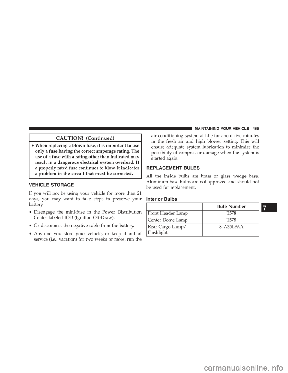
CAUTION! (Continued)
•When replacing a blown fuse, it is important to use
only a fuse having the correct amperage rating. The
use of a fuse with a rating other than indicated may
result in a dangerous electrical system overload. If
a properly rated fuse continues to blow, it indicates
a problem in the circuit that must be corrected.
VEHICLE STORAGE
If you will not be using your vehicle for more than 21
days, you may want to take steps to preserve your
battery.
• Disengage the mini-fuse in the Power Distribution
Center labeled IOD (Ignition Off-Draw).
• Or disconnect the negative cable from the battery.
• Anytime you store your vehicle, or keep it out of
service (i.e., vacation) for two weeks or more, run the air conditioning system at idle for about five minutes
in the fresh air and high blower setting. This will
ensure adequate system lubrication to minimize the
possibility of compressor damage when the system is
started again.
REPLACEMENT BULBS
All the inside bulbs are brass or glass wedge base.
Aluminum base bulbs are not approved and should not
be used for replacement.
Interior Bulbs
Bulb Number
Front Header Lamp T578
Center Dome Lamp T578
Rear Cargo Lamp/
Flashlight 8–A35LFAA7
MAINTAINING YOUR VEHICLE 469
Page 503 of 517

Flooded Engine Starting....................317
Fluid, Brake ............................ .474
Fluid Capacities ......................... .472
Fluid Leaks ............................ .101
Fluid Level Checks Automatic Transmission ..................456
Cooling System ....................... .448
Power Steering ....................... .333
Fluids, Lubricants and Genuine Parts ...........473
Fog Lights ............................. .164
Folding Rear Seat ........................ .158
Folding Rear Seat (Sedan) ...................158
Four Wheel Drive ........................ .331
Systems ............................ .331
Four Wheel Drive Operation .................331
Freeing A Stuck Vehicle .....................423
Fuel .................................. .381
Adding ............................. .386
Additives ........................... .384Capacity
............................ .472
Clean Air ........................... .382
Ethanol ............................. .382
Filler Cap (Gas Cap) ....................386
Gasoline ............................ .381
Gauge .............................. .212
Light .............................. .213
Materials Added ...................... .384
Methanol ........................... .382
Octane Rating ........................ .381
Requirements ........................ .381
Tank Capacity ........................ .472
Fueling ............................... .386
Fuel System Caution ...................... .387
Fuses ................................. .465
Garage Door Opener (HomeLink �)
.............176
Gas Cap (Fuel Filler Cap) ...................386
Gasoline, Clean Air ....................... .382
10
INDEX 499
Page 505 of 517

Ignition Key Removal.......................12
Immobilizer (Sentry Key) ....................15
Infant Restraint ...........................76
Information Center, Vehicle ..................228
Inside Rearview Mirror .....................107
Instrument Cluster ....................... .212
Instrument Panel and Controls ................210
Instrument Panel Cover .....................464
Instrument Panel Lens Cleaning ...............464
Integrated Power Module (Fuses) ..............465
Interior Appearance Care ....................462
Intermittent Wipers (Delay Wipers) .............170
Introduction ..............................4
Jacking Instructions ....................... .410
Jack Location ........................... .408
Jack Operation .......................... .408
Jump Starting ........................... .419Key-In Reminder
..........................14
Keyless Entry System (Sedan) .................20
Key, Programming .........................17
Key, Replacement ..........................16
Keys ...................................12
Key, Sentry (Immobilizer) ....................15
Knee Bolster ..............................61
Lane Change and Turn Signals ................471
Lane Change Assist ....................... .165
Lap/Shoulder Belts .........................43
Latches ............................... .101
Hood .............................. .160
Lead Free Gasoline ....................... .381
Leaks, Fluid ............................ .101
Life of Tires ............................ .367
Liftgate (Sedan) ...........................37
Liftgate Window Wiper/Washer ...............202
Light Bulbs ............................. .101
10
INDEX 501
Page 516 of 517

INSTALLATION OF RADIO TRANSMITTING
EQUIPMENTSpecial design considerations are incorporated into this
vehicle’s electronic system to provide immunity to radio
frequency signals. Mobile two-way radios and telephone
equipment must be installed properly by trained personnel.
The following must be observed during installation.
The positive power connection should be made directly to
the battery and fused as close to the battery as possible. The
negative power connection should be made to body sheet
metal adjacent to the negative battery connection. This
connection should not be fused.
Antennas for two-way radios should be mounted on the roof
or the rear area of the vehicle. Care should be used in
mounting antennas with magnet bases. Magnets may affect
the accuracy or operation of the compass on vehicles so
equipped.The antenna cable should be as short as practical and
routed away from the vehicle wiring when possible. Use only
fully shielded coaxial cable.
Carefully match the antenna and cable to the radio to ensure
a low Standing Wave Ratio (SWR).
Mobile radio equipment with output power greater than
normal may require special precautions.
All installations should be checked for possible interference
between the communications equipment and the vehicle’s
electronic systems.