2013 HYUNDAI VELOSTER height
[x] Cancel search: heightPage 75 of 372
357
Safety features of your vehicle
Additional safety precautions
Never let passengers ride in the
cargo area or on top of a folded-
down back seat.All occupants should
sit upright, fully back in their seats with
their seat belts on and their feet on the
floor.
Passengers should not move out of
or change seats while the vehicle is
moving.A passenger who is not wear-
ing a seat belt during a crash or emer-
gency stop can be thrown against the
inside of the vehicle, against other
occupants, or out of the vehicle.
Each seat belt is designed to
restrain one occupant.If more than
one person uses the same seat belt,
they could be seriously injured or killed
in a collision.
Do not use any accessories on seat
belts.Devices claiming to improve
occupant comfort or reposition the seat
belt can reduce the protection provided
by the seat belt and increase the
chance of serious injury in a crash.
Passengers should not place hard
or sharp objects between them-
selves and the air bags.Carrying
hard or sharp objects on your lap or in
your mouth can result in injuries if an
air bag inflates.Keep occupants away from the air
bag covers.All occupants should sit
upright, fully back in their seats with
their seat belts on and their feet on the
floor. If occupants are too close to the
air bag covers, they could be injured if
the air bags inflate.
Do not attach or place objects on or
near the air bag covers.Any object
attached to or placed on the front or
side air bag covers could interfere with
the proper operation of the air bags.
Do not modify the front seats.
Modification of the front seats could
interfere with the operation of the sup-
plemental restraint system sensing
components or side air bags.
Do not place items under the front
seats.Placing items under the front
seats could interfere with the operation
of the supplemental restraint system
sensing components and wiring har-
nesses.
Never hold an infant or child on your
lap.The infant or child could be seri-
ously injured or killed in the event of a
crash. All infants and children should
be properly restrained in appropriate
child safety seats or seat belts in the
rear seat.
Adding equipment to or modifying
your air bag-equipped vehicle
If you modify your vehicle by changing
your vehicle's frame, bumper system,
front end or side sheet metal or ride
height, this may affect the operation of
your vehicle's air bag system.
WARNING
Sitting improperly or out of posi-
tion can cause occupants to be
shifted too close to a deploying
air bag, strike the interior struc-
ture or be thrown from the vehicle
resulting in serious injury or
death.
Always sit upright with the seat-
back in an upright position, cen-
tered on the seat cushion with
your seat belt on, legs comfort-
ably extended and your feet on
the floor.
Be careful not to cause impact to
the doors when the ignition is
ON. The air bags may inflate.
Page 115 of 372
439
Features of your vehicle
(Continued)
• When the charging system warning
light comes on or the voltage is low
(When the alternator (or battery) does
not operate normally or it malfunc-
tions), the steering wheel increase and
become difficult to control normal.Tilt steering / Tilt and telescope
steering
Tilt steering allows you to adjust the
steering wheel before you drive. You can
also raise it to give your legs more room
when you exit and enter the vehicle.
The steering wheel should be positioned
so that it is comfortable for you to drive,
while permitting you to see the instru-
ment panel warning lights and gauges.
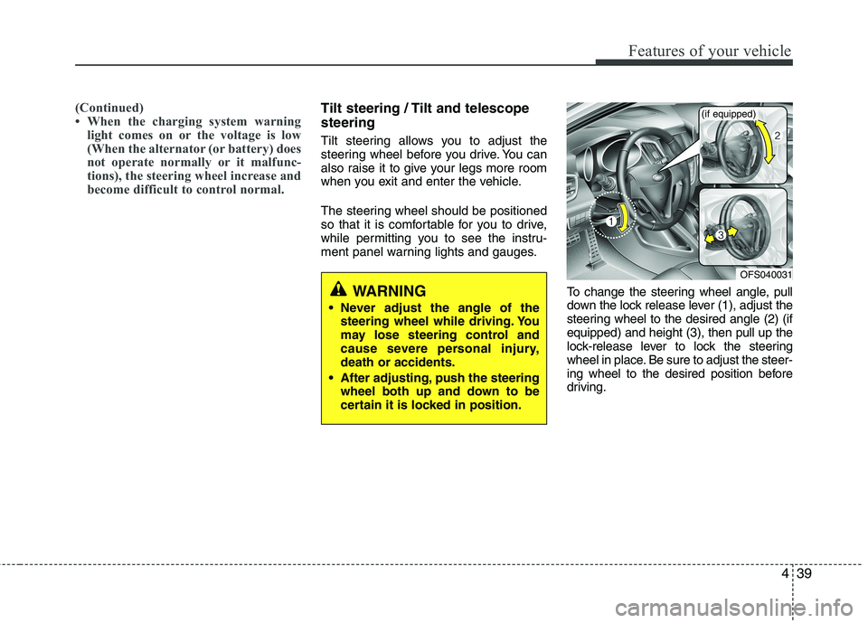
To change the steering wheel angle, pull
down the lock release lever (1), adjust the
steering wheel to the desired angle (2) (if
equipped) and height (3), then pull up the
lock-release lever to lock the steering
wheel in place. Be sure to adjust the steer-
ing wheel to the desired position before
driving.
WARNING
Never adjust the angle of the
steering wheel while driving. You
may lose steering control and
cause severe personal injury,
death or accidents.
After adjusting, push the steering
wheel both up and down to be
certain it is locked in position.
OFS040031
(if equipped)
Page 140 of 372

Features of your vehicle
64 4
The detecting range may decrease
when:
1. The sensor is stained with foreign mat-
ter such as snow or water. (The sens-
ing range will return to normal when
removed.)
2. Outside air temperature is extremely
hot or cold.
The following objects may not be rec-
ognized by the sensor:
1. Sharp or slim objects such as ropes,
chains or small poles.
2. Objects which tend to absorb the sen-
sor frequency such as clothes, spongy
material or snow.
3. Undetectable objects smaller than 40 in.
(1 m) and narrower than 6 in. (14 cm) in
diameter.Rear parking assist system pre-
cautions
The rear parking assist system may
not sound sequentially depending on
the speed and shapes of the objects
detected.
The rear parking assist system may
malfunction if the vehicle bumper
height or sensor installation has been
modified or damaged. Any non-factory
installed equipment or accessories
may also interfere with the sensor per-
formance.
The sensor may not recognize objects
less than 15 in. (40 cm) from the sen-
sor, or it may sense an incorrect dis-
tance. Use caution.
When the sensor is frozen or stained
with snow, dirt, or water, the sensor
may be inoperative until the stains are
removed using a soft cloth.
Do not push, scratch or strike the sen-
sor. Sensor damage could occur.
✽ ✽
NOTICE
This system can only sense objects with-
in the range and location of the sensors;
it can not detect objects in other areas
where sensors are not installed. Also,
small or slim objects, such as poles or
objects located between sensors may not
be detected by the sensors.
Always visually check behind the vehi-
cle when backing up.
Be sure to inform any drivers of the
vehicle that may be unfamiliar with the
system regarding the systems capabili-
ties and limitations.
WARNING
Pay close attention when the vehi-
cle is driven close to objects on the
road, particularly pedestrians, and
especially children. Be aware that
some objects may not be detected
by the sensors, due to the object’s
distance, size or material, all of
which can limit the effectiveness of
the sensor. Always perform a visu-
al inspection to make sure the vehi-
cle is clear of all obstructions
before moving the vehicle in any
direction.
Page 208 of 372
527
Driving your vehicle
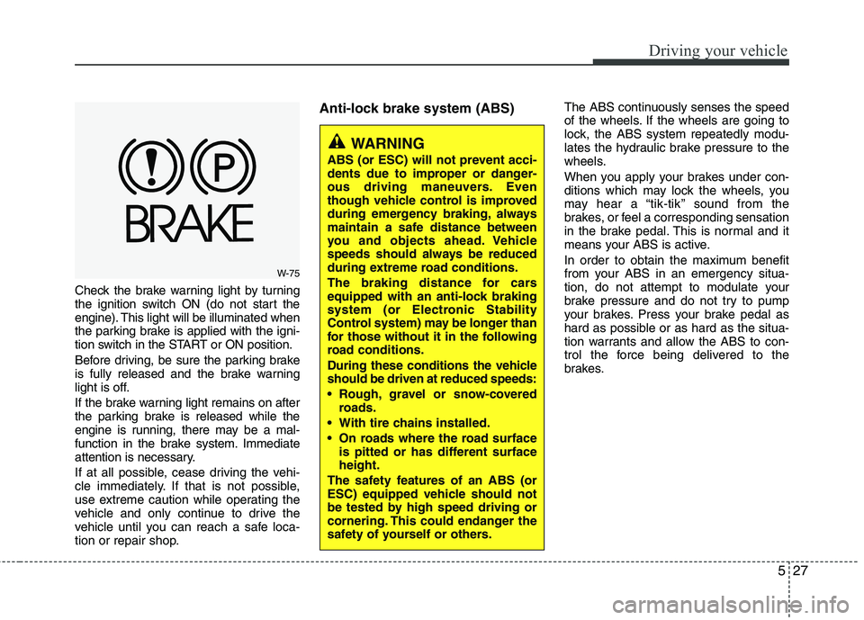
Check the brake warning light by turning
the ignition switch ON (do not start the
engine). This light will be illuminated when
the parking brake is applied with the igni-
tion switch in the START or ON position.
Before driving, be sure the parking brake
is fully released and the brake warning
light is off.
If the brake warning light remains on after
the parking brake is released while the
engine is running, there may be a mal-
function in the brake system. Immediate
attention is necessary.
If at all possible, cease driving the vehi-
cle immediately. If that is not possible,
use extreme caution while operating the
vehicle and only continue to drive the
vehicle until you can reach a safe loca-
tion or repair shop.
Anti-lock brake system (ABS)The ABS continuously senses the speed
of the wheels. If the wheels are going to
lock, the ABS system repeatedly modu-
lates the hydraulic brake pressure to the
wheels.
When you apply your brakes under con-
ditions which may lock the wheels, you
may hear a “tik-tik’’ sound from the
brakes, or feel a corresponding sensation
in the brake pedal. This is normal and it
means your ABS is active.
In order to obtain the maximum benefit
from your ABS in an emergency situa-
tion, do not attempt to modulate your
brake pressure and do not try to pump
your brakes. Press your brake pedal as
hard as possible or as hard as the situa-
tion warrants and allow the ABS to con-
trol the force being delivered to the
brakes.
WARNING
ABS (or ESC) will not prevent acci-
dents due to improper or danger-
ous driving maneuvers. Even
though vehicle control is improved
during emergency braking, always
maintain a safe distance between
you and objects ahead. Vehicle
speeds should always be reduced
during extreme road conditions.
The braking distance for cars
equipped with an anti-lock braking
system (or Electronic Stability
Control system) may be longer than
for those without it in the following
road conditions.
During these conditions the vehicle
should be driven at reduced speeds:
Rough, gravel or snow-covered
roads.
With tire chains installed.
On roads where the road surface
is pitted or has different surface
height.
The safety features of an ABS (or
ESC) equipped vehicle should not
be tested by high speed driving or
cornering. This could endanger the
safety of yourself or others.
W-75
Page 319 of 372
Maintenance
54 7
Compact spare tire replacement
(if equipped)
A compact spare tire has a shorter
tread life than a regular size tire.
Replace it when you can see the
tread wear indicator bars on the tire.
The replacement compact spare tire
should be the same size and design
tire as the one provided with your
new vehicle and should be mounted
on the same compact spare tire
wheel. The compact spare tire is not
designed to be mounted on a regular
size wheel, and the compact spare
tire wheel is not designed for mount-
ing a regular size tire.Wheel replacement
When replacing the metal wheels for
any reason, make sure the new
wheels are equivalent to the original
factory units in diameter, rim width
and offset.Tire traction
Tire traction can be reduced if you
drive on worn tires, tires that are
improperly inflated or on slippery
road surfaces. Tires should be
replaced when tread wear indicators
appear. To reduce the possibility of
losing control, slow down whenever
there is rain, snow or ice on the road.
Tire maintenance
In addition to proper inflation, correct
wheel alignment helps to decrease
tire wear. If you find a tire is worn
unevenly, have your dealer check the
wheel alignment.
When you have new tires installed,
make sure they are balanced. This
will increase vehicle ride comfort and
tire life. Additionally, a tire should
always be rebalanced if it is removed
from the wheel.
WARNING
A wheel that is not the correct
size may adversely affect wheel
and bearing life, braking and
stopping abilities, handling char-
acteristics, ground clearance,
body-to-tire clearance, snow
chain clearance, speedometer
and odometer calibration, head-
light aim and bumper height.
Page 320 of 372
755
Maintenance
Tire sidewall labeling
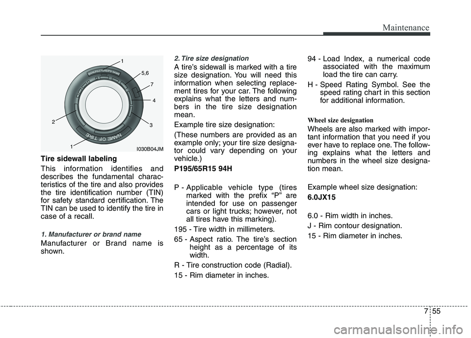
This information identifies and
describes the fundamental charac-
teristics of the tire and also provides
the tire identification number (TIN)
for safety standard certification. The
TIN can be used to identify the tire in
case of a recall.
1. Manufacturer or brand name
Manufacturer or Brand name is
shown.
2. Tire size designation
A tire’s sidewall is marked with a tire
size designation. You will need this
information when selecting replace-
ment tires for your car. The following
explains what the letters and num-
bers in the tire size designation
mean.
Example tire size designation:
(These numbers are provided as an
example only; your tire size designa-
tor could vary depending on your
vehicle.)
P195/65R15 94H
P - Applicable vehicle type (tires
marked with the prefix “P’’ are
intended for use on passenger
cars or light trucks; however, not
all tires have this marking).
195 - Tire width in millimeters.
65 - Aspect ratio. The tire’s section
height as a percentage of its
width.
R - Tire construction code (Radial).
15 - Rim diameter in inches.94 - Load Index, a numerical code
associated with the maximum
load the tire can carry.
H - Speed Rating Symbol. See the
speed rating chart in this section
for additional information.
Wheel size designation
Wheels are also marked with impor-
tant information that you need if you
ever have to replace one. The follow-
ing explains what the letters and
numbers in the wheel size designa-
tion mean.
Example wheel size designation:
6.0JX15
6.0 - Rim width in inches.
J - Rim contour designation.
15 - Rim diameter in inches.
I030B04JM 1
1 2
34 5,6
7
Page 323 of 372
Maintenance
58 7
Temperature -A, B & C
The temperature grades are A (the
highest), B and C representing the
tire’s resistance to the generation of
heat and its ability to dissipate heat
when tested under controlled condi-
tions on a specified indoor laboratory
test wheel.
Sustained high temperature can
cause the material of the tire to
degenerate and reduce tire life, and
excessive temperature can lead to
sudden tire failure. The grade C cor-
responds to a level of performance
which all passenger car tires must
meet under the Federal Motor
Vehicle Safety Standard No. 109.
Grades B and A represent higher
levels of performance on the labora-
tory test wheel than the minimum
required by law.Tire terminology and definitions
Air Pressure: The amount of air
inside the tire pressing outward on
the tire. Air pressure is expressed in
pounds per square inch (psi) or kilo-
pascal (kPa).
Accessory Weight: This means the
combined weight of optional acces-
sories. Some examples of optional
accessories are, EcoShift dual clutch
transmission, power seats, and air
conditioning.
Aspect Ratio: The relationship of a
tire's height to its width.
Belt:A rubber coated layer of cords
that is located between the plies and
the tread. Cords may be made from
steel or other reinforcing materials.
Bead: The tire bead contains steel
wires wrapped by steel cords that
hold the tire onto the rim.
Bias Ply Tire: A pneumatic tire in
which the plies are laid at alternate
angles less than 90 degrees to the
centerline of the tread.WARNING - Tire
temperature
The temperature grade for this
tire is established for a tire that
is properly inflated and not
overloaded. Excessive speed,
underinflation, or excessive
loading, either separately or in
combination, can cause heat
build-up and possible sudden
tire failure. This can cause loss
of vehicle control and serious
injury or death.
Page 355 of 372

Specifications, Consumer information, Reporting safety defects
2 8
ENGINE
DIMENSIONS
Itemin. (mm)
GDI Turbo GDI
Overall length 166.1 (4220) 167.3 (4250)
Overall width 70.5 (1790) 71.1 (1805)
Overall height 55.1 (1399) 55.1 (1399)
Front treadP215/45 R17 61.5 (1561) -
215/40 R18 61.3 (1557) -
P215/40 R18 - 61.3 (1557)
Rear treadP215/45 R17 62.0 (1574) -
215/40 R18 61.8 (1570) -
P215/40 R18 - 61.8 (1570)
Wheelbase 104.3 (2650) 104.3 (2650)
ItemGasoline
Displacement
cu. in (cc) 97.09 (1591)
Bore x Stroke
in. (mm)3.03x3.36 (77x85.44)
Firing order 1-3-4-2
No. of cylinders 4, In-line
BULB WATTAGE
Light BulbWattageBulb type
HeadlightsHigh55H7
Low55H7HPLL/H11B*
Front turn signal lights27PY27W
Position lightsLEDLED
Sidemarker5W5W
Front fog lights*GDI27GE881
Turbo GDI35H8
Side repeaterLEDLED
Stop and tail lights28/8P28/8W
Rear turn signal lights 27PY27W
Back-up lights16W16W
High mounted stop lightLEDLED
License plate lights5W5W
Front map lamp8FESTOON 8W
Center room lamp*8FESTOON 8W
Luggage room lamp5FESTOON 5W
* : If equipped