Page 297 of 397
621
What to do in an emergency
When towing your vehicle in an emer- gency without wheel dollies :
1. Set the ignition switch in the ACC posi-tion.
2. Place the transaxle shift lever in N (Neutral).
3. Release the parking brake.
Removable towing hook (rear)
1. Open the tailgate, and remove the tow- ing hook from the tool case.
2. Remove the hole cover pressing the lower part of the cover on the rear
bumper.
3. Install the towing hook by turning it clockwise into the hole until it is fullysecured.
4. Remove the towing hook and install the cover after use.
Emergency towing
If towing is necessary, we recommend
you to have it done by an authorized
HYUNDAI dealer or a commercial tow
truck service.
CAUTION
Failure to place the transaxle shift
lever in N (Neutral) may cause inter-
nal damage to the transaxle.
OLM069016L
OLM069014
OLM069015
■ Front
■Rear
Page 299 of 397
623
What to do in an emergency
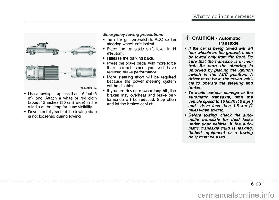
Use a towing strap less than 16 feet (5m) long. Attach a white or red cloth (about 12 inches (30 cm) wide) in the
middle of the strap for easy visibility.
Drive carefully so that the towing strap is not loosened during towing.
Emergency towing precautions
Turn the ignition switch to ACC so the
steering wheel isn’t locked.
Place the transaxle shift lever in N (Neutral).
Release the parking bake.
Press the brake pedal with more force than normal since you will have
reduced brake performance.
More steering effort will be required because the power steering system
will be disabled.
If you are driving down a long hill, the brakes may overheat and brake per-
formance will be reduced. Stop often
and let the brakes cool off.
OEN066014
CAUTION - Automatic transaxle
If the car is being towed with all
four wheels on the ground, it canbe towed only from the front. Be
sure that the transaxle is in neu-tral. Be sure the steering isunlocked by placing the ignition switch in the ACC position. A
driver must be in the towed vehi- cle to operate the steering andbrakes.
To avoid serious damage to the automatic transaxle, limit thevehicle speed to 15 km/h (10 mph)and drive less than 1.5 km (1
mile) when towing.
Before towing, check the auto- matic transaxle for fluid leaks
under your vehicle. If the auto-matic transaxle fluid is leaking,flatbed equipment or a towingdolly must be used.
Page 335 of 397
735
Maintenance
Battery recharging
Your vehicle has a maintenance-free,
calcium-based battery.
If the battery becomes discharged in ashort time (because, for example, the
headlights or interior lights were left on
while the vehicle was not in use),
recharge it by slow charging (trickle)
for 10 hours.
If the battery gradually discharges because of high electric load while the
vehicle is being used, recharge it at 20-
30A for two hours.(Continued)
When lifting a plastic-cased bat-tery, excessive pressure on the
case may cause battery acid to
leak, resulting in personal injury.
Lift with a battery carrier or with
your hands on opposite corners.
Never attempt to recharge the battery when the battery cablesare connected.
The electrical ignition system works with high voltage. Never
touch these components with the engine running or the ignition
switched on.
Failure to follow the above warn-
ings can result in serious bodily
injury or death.
WARNING- Recharging battery
When recharging the battery,
observe the following precautions:
The battery must be removed from the vehicle and placed in an area with good ventilation.
Do not allow cigarettes, sparks, or flame near the battery.
Watch the battery during charg- ing, and stop or reduce the charg-
ing rate if the battery cells begin
gassing (boiling) violently or if
the temperature of the electrolyte
of any cell exceeds 120°F (49°C).
(Continued)
CALIFORNIA PROPOSI-
TION 65 WARNING
Battery posts, terminals, and relat- ed accessories contain lead and
lead compounds, chemicals known
to the State of California to cause
cancer, birth defects, and reproduc-
tive harm. Batteries also contain
other chemicals known to the State
of California to cause cancer. Wash hands after handling.
CAUTION
If you connect unauthorized elec- tronic devices to the battery, thebattery may be discharged. Never
use unauthorized devices.
Page 351 of 397
751
Maintenance
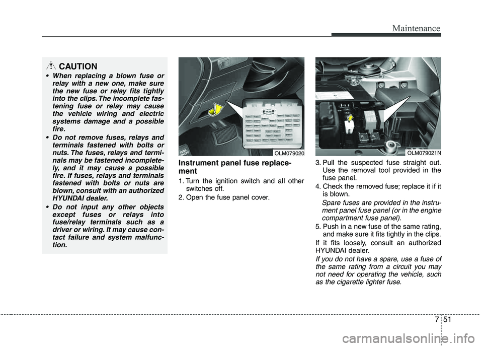
Instrument panel fuse replace- ment
1. Turn the ignition switch and all otherswitches off.
2. Open the fuse panel cover. 3. Pull the suspected fuse straight out.
Use the removal tool provided in the fuse panel.
4. Check the removed fuse; replace it if it is blown.
Spare fuses are provided in the instru-
ment panel fuse panel (or in the engine compartment fuse panel).
5. Push in a new fuse of the same rating, and make sure it fits tightly in the clips.
If it fits loosely, consult an authorized
HYUNDAI dealer.
If you do not have a spare, use a fuse of the same rating from a circuit you maynot need for operating the vehicle, suchas the cigarette lighter fuse.
OLM079020OLM079021N
CAUTION
When replacing a blown fuse or
relay with a new one, make surethe new fuse or relay fits tightly
into the clips. The incomplete fas-tening fuse or relay may cause the vehicle wiring and electricsystems damage and a possible
fire.
Do not remove fuses, relays and terminals fastened with bolts or
nuts. The fuses, relays and termi-nals may be fastened incomplete-ly, and it may cause a possible fire. If fuses, relays and terminals
fastened with bolts or nuts are blown, consult with an authorizedHYUNDAI dealer.
Do not input any other objects except fuses or relays intofuse/relay terminals such as adriver or wiring. It may cause con-
tact failure and system malfunc-tion.
Page 353 of 397
753
Maintenance
Engine compartment fuse replacement
1. Turn the ignition switch and all otherswitches off.
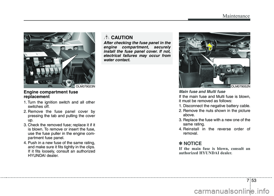
2. Remove the fuse panel cover by pressing the tab and pulling the cover
up.
3. Check the removed fuse; replace it if it is blown. To remove or insert the fuse,use the fuse puller in the engine com-
partment fuse panel.
4. Push in a new fuse of the same rating, and make sure it fits tightly in the clips.
If it fits loosely, consult an authorized
HYUNDAI dealer.
Main fuse and Multi fuse
If the main fuse and Multi fuse is blown,
it must be removed as follows:
1. Disconnect the negative battery cable.
2. Remove the nuts shown in the picture
above.
3. Replace the fuse with a new one of the same rating.
4. Reinstall in the reverse order of removal.
✽✽ NOTICE
If the main fuse is blown, consult an
authorized HYUNDAI dealer.
CAUTION
After checking the fuse panel in the engine compartment, securelyinstall the fuse panel cover. If not,
electrical failures may occur fromwater contact.
OLM079052NOLM079023N
Page 357 of 397
757
Maintenance
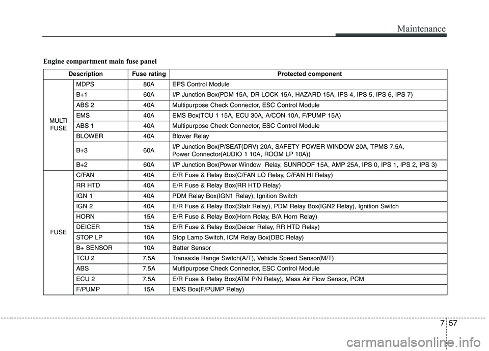
Engine compartment main fuse panel
Description Fuse ratingProtected component
MULTI FUSE MDPS 80A EPS Control Module
B+1 60A I/P Junction Box(PDM 15A, DR LOCK 15A, HAZARD 15A, IPS 4, IPS 5, IPS 6, IPS 7)
ABS 2 40A Multipurpose Check Connector, ESC Control Module
EMS 40A EMS Box(TCU 1 15A, ECU 30A, A/CON 10A, F/PUMP 15A)
ABS 1 40A Multipurpose Check Connector, ESC Control Module
BLOWER 40A Blower Relay
B+3 60A
I/P Junction Box(P/SEAT(DRV) 20A, SAFETY POWER WINDOW 20A, TPMS 7.5A,
Power Connector(AUDIO 1 10A, ROOM LP 10A))
B+2 60A I/P Junction Box(Power Window Relay, SUNROOF 15A, AMP 25A, IPS 0, IPS 1, IPS 2, IPS 3)
FUSE C/FAN 40A E/R Fuse & Relay Box(C/FAN LO Relay, C/FAN HI Relay)
RR HTD 40A E/R Fuse & Relay Box(RR HTD Relay)
IGN 1 40A PDM Relay Box(IGN1 Relay), Ignition Switch
IGN 2 40A E/R Fuse & Relay Box(Statr Relay), PDM Relay Box(IGN2 Relay), Ignition Switch
HORN 15A E/R Fuse & Relay Box(Horn Relay, B/A Horn Relay)
DEICER 15A E/R Fuse & Relay Box(Deicer Relay, RR HTD Relay)
STOP LP 10A Stop Lamp Switch, ICM Relay Box(DBC Relay)
B+ SENSOR 10A Batter Sensor
TCU 2 7.5A Transaxle Range Switch(A/T), Vehicle Speed Sensor(M/T)
ABS 7.5A Multipurpose Check Connector, ESC Control Module
ECU 2 7.5A E/R Fuse & Relay Box(ATM P/N Relay), Mass Air Flow Sensor, PCM
F/PUMP 15A EMS Box(F/PUMP Relay)
Page 358 of 397
Maintenance
58
7
Description Fuse rating Protected component
FUSE SENSOR 4 15A
E/R Fuse & Relay Box(C/FAN HI, LO Relay), EMS Box(F/PUMP Relay),
Oxygen Sensor (UP, DOWN), PCM
SENSOR 3 10A EMS Box(A/CON Relay), Injector(#1, #2, #3, #4)
SENSOR 2 10A -
TCU 1 15A PCM
A/CON 10A EMS Box(A/CON Relay)
SENSOR 1 10A Crankshaft Position Sensor, Camshaft Position Sensor #1/2, Oil Control Valve #1/2,
Canister Purge Control Solenoid Valve, Variable Intake Manifold Valve, Canister Close Valve
ECU 1 20A Ignition Colil (#1, #2, #3, #4), Condenser
ECU 30A EMS Box(Engine Control Relay)
Page 359 of 397
759
Maintenance
LIGHT BULBS
Use only the bulbs of the specifiedwattage.
✽✽ NOTICE
After heavy, driving rain or washing,
headlight and taillight lenses could
appear frosty. This condition is caused by
the temperature difference between the
lamp inside and outside. This is similar
to the condensation on your windows
inside your vehicle during the rain and
doesn’t indicate a problem with your
vehicle. If the water leaks into the lamp
bulb circuitry, have the vehicle checked
by an authorized HYUNDAI dealer.
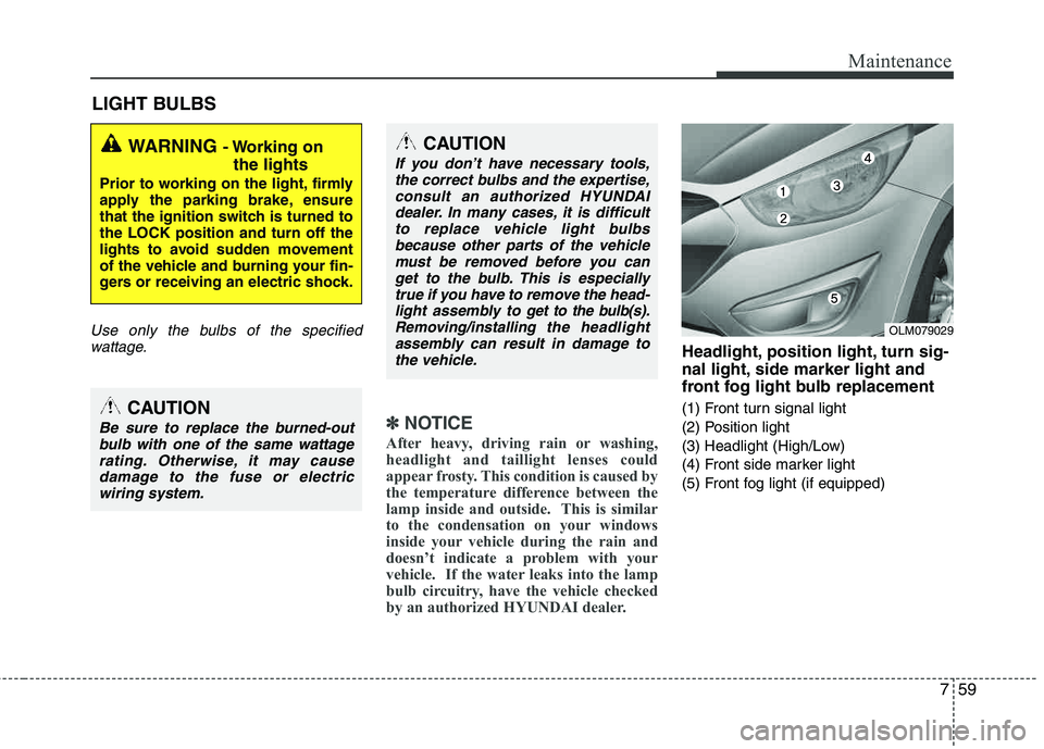
Headlight, position light, turn sig-
nal light, side marker light and
front fog light bulb replacement
(1) Front turn signal light
(2) Position light
(3) Headlight (High/Low)
(4) Front side marker light
(5) Front fog light (if equipped)
WARNING - Working on the lights
Prior to working on the light, firmly
apply the parking brake, ensure
that the ignition switch is turned tothe LOCK position and turn off the
lights to avoid sudden movement
of the vehicle and burning your fin-
gers or receiving an electric shock.
CAUTION
Be sure to replace the burned-outbulb with one of the same wattagerating. Otherwise, it may cause damage to the fuse or electric
wiring system.
CAUTION
If you don’t have necessary tools, the correct bulbs and the expertise,consult an authorized HYUNDAI
dealer. In many cases, it is difficultto replace vehicle light bulbsbecause other parts of the vehiclemust be removed before you can
get to the bulb. This is especiallytrue if you have to remove the head-light assembly to
get to the bulb(s).
Removing/installingthe headlight
assembly can result in damage to
the vehicle.OLM079029