2013 Hyundai Sonata Hybrid fuses
[x] Cancel search: fusesPage 190 of 425
Features of your vehicle
110 4
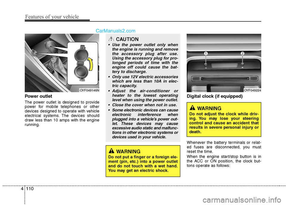
Power outlet
The power outlet is designed to provide
power for mobile telephones or other
devices designed to operate with vehicle
electrical systems. The devices should
draw less than 10 amps with the engine
running.
Digital clock (if equipped)
Whenever the battery terminals or relat-
ed fuses are disconnected, you must
reset the time.
When the engine start/stop button is in
the ACC or ON position, the clock but-
tons operate as follows:
CAUTION
Use the power outlet only when
the engine is running and remove
the accessory plug after use.
Using the accessory plug for pro-
longed periods of time with the
engine off could cause the bat-
tery to discharge.
Only use 12V electric accessories
which are less than 10A in elec-
tric capacity.
Adjust the air-conditioner or
heater to the lowest operating
level when using the power outlet.
Close the cover when not in use.
Some electronic devices can cause
electronic interference when
plugged into a vehicle’s power out-
let. These devices may cause
excessive audio static and malfunc-
tions in other electronic systems or
devices used in your vehicle.
WARNING
Do not put a finger or a foreign ele-
ment (pin, etc.) into a power outlet
and do not touch with a wet hand.
You may get an electric shock.
OYF049146NOYF049224
WARNING
Do not adjust the clock while driv-
ing. You may lose your steering
control and cause an accident that
results in severe personal injury or
death.
Page 315 of 425
7
Engine compartment / 7-2
Maintenance services / 7-3
Owner maintenance / 7-5
Scheduled maintenance service / 7-7
Explanation of scheduled maintenance items / 7-19
Engine oil / 7-22
Inverter coolant / 7-24
Engine coolant / 7-24
Brake fluid / 7-27
Washer fluid / 7-28
Parking brake / 7-28
Air cleaner / 7-29
Climate control air filter / 7-30
Wiper blades / 7-32
Battery (12V) / 7-34
Tires and wheels / 7-37
Fuses / 7-50
Light bulbs / 7-60
Appearance care / 7-69
Emission control system / 7-75
High voltage battery / 7-78
California perchlorate notice / 7-78
Maintenance
Page 364 of 425

Maintenance
50 7
FUSES
A vehicle’s electrical system is protected
from electrical overload damage by fuses.
This vehicle has 2 fuse panels, one locat-
ed in the driver’s side panel bolster, the
other in the engine compartment.
If any of your vehicle’s lights, accessories,
or controls do not work, check the appro-
priate circuit fuse. If a fuse has blown, the
element inside the fuse will be melted.
If the electrical system does not work,
first check the driver’s side fuse panel.Before replacing a blown fuse, discon-
nect the negative battery cable.
Always replace a blown fuse with one of
the same rating.
If the replacement fuse blows, this indi-
cates an electrical problem. Avoid using
the system involved and immediately
consult an authorized HYUNDAI dealer.
Three kinds of fuses are used: blade type
for lower amperage rating, cartridge type,
and multi fuse for higher amperage ratings.
✽ ✽
NOTICE
The actual fuse/relay panel label may
differ from equipped items.
WARNING - Fuse
replacement
Never replace a fuse with anything
but another fuse of the same rat-
ing.
A higher capacity fuse could
cause damage and possibly a fire.
Never install a wire or aluminum
foil instead of the proper fuse -
even as a temporary repair. It may
cause extensive wiring damage
and a possible fire.
CAUTION
Do not use a screwdriver or any
other metal object to remove fuses
because it may cause a short circuit
and damage the system.
CAUTION
When replacing a blown fuse or
relay with a new one, make sure
the new fuse or relay fits tightly
into the clips. The incomplete fas-
tening fuse or relay may cause the
vehicle wiring and electric sys-
tems damage and a possible fire.
Do not remove fuses, relays and
terminals fastened with bolts or
nuts. The fuses, relays and termi-
nals may be fastened incomplete-
ly, and it may cause a possible
fire. If fuses, relays and terminals
fastened with bolts or nuts are
blown, consult with an authorized
HYUNDAI dealer.
Do not input any other objects
except fuses or relays into
fuse/relay terminals such as a driv-
er or wiring. It may cause contact
failure and system malfunction.
OBK079042 Normal Normal Blade type
Cartridge type
Multi fuseBlown
Blown
Normal Blown
Page 365 of 425
751
Maintenance
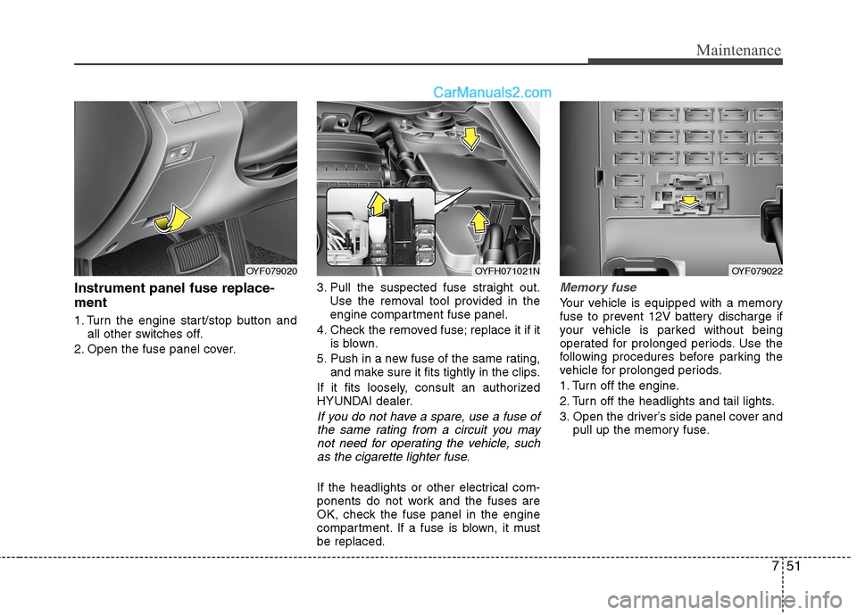
Instrument panel fuse replace-
ment
1. Turn the engine start/stop button and
all other switches off.
2. Open the fuse panel cover.3. Pull the suspected fuse straight out.
Use the removal tool provided in the
engine compartment fuse panel.
4. Check the removed fuse; replace it if it
is blown.
5. Push in a new fuse of the same rating,
and make sure it fits tightly in the clips.
If it fits loosely, consult an authorized
HYUNDAI dealer.
If you do not have a spare, use a fuse of
the same rating from a circuit you may
not need for operating the vehicle, such
as the cigarette lighter fuse.
If the headlights or other electrical com-
ponents do not work and the fuses are
OK, check the fuse panel in the engine
compartment. If a fuse is blown, it must
be replaced.
Memory fuse
Your vehicle is equipped with a memory
fuse to prevent 12V battery discharge if
your vehicle is parked without being
operated for prolonged periods. Use the
following procedures before parking the
vehicle for prolonged periods.
1. Turn off the engine.
2. Turn off the headlights and tail lights.
3. Open the driver’s side panel cover and
pull up the memory fuse.
OYF079020OYFH071021NOYF079022
Page 373 of 425
759
Maintenance
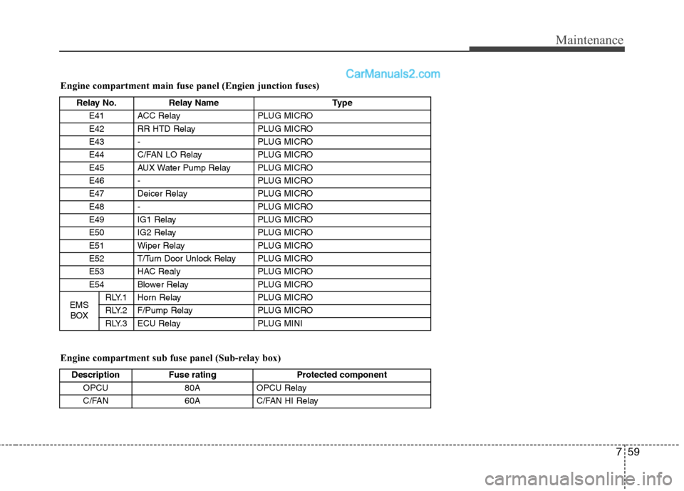
Engine compartment sub fuse panel (Sub-relay box) Engine compartment main fuse panel (Engien junction fuses)
Description Fuse rating Protected component
OPCU 80A OPCU Relay
C/FAN 60A C/FAN HI Relay
Relay No. Relay Name Type
E41 ACC Relay PLUG MICRO
E42 RR HTD Relay PLUG MICRO
E43 - PLUG MICRO
E44 C/FAN LO Relay PLUG MICRO
E45 AUX Water Pump Relay PLUG MICRO
E46 - PLUG MICRO
E47 Deicer Relay PLUG MICRO
E48 - PLUG MICRO
E49 IG1 Relay PLUG MICRO
E50 IG2 Relay PLUG MICRO
E51 Wiper Relay PLUG MICRO
E52 T/Turn Door Unlock RelayPLUG MICRO
E53 HAC Realy PLUG MICRO
E54 Blower Relay PLUG MICRO
EMS
BOXRLY.1 Horn Relay PLUG MICRO
RLY.2 F/Pump Relay PLUG MICRO
RLY.3 ECU Relay PLUG MINI
Page 410 of 425
H8
THE COMPONENTS OF HYBRID VEHICLE (CONT.)
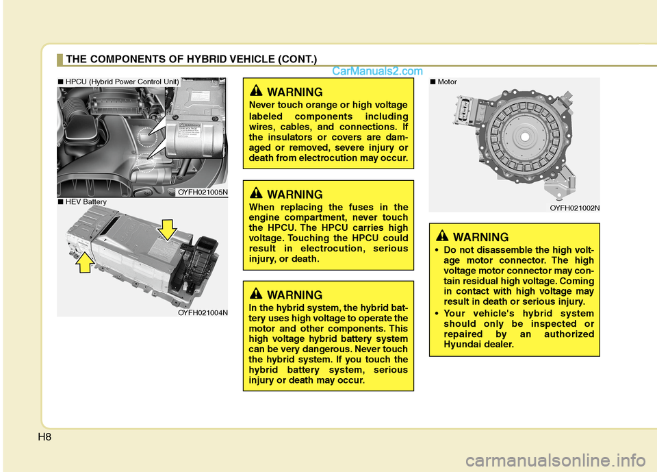
WARNING
In the hybrid system, the hybrid bat-
tery uses high voltage to operate the
motor and other components. This
high voltage hybrid battery system
can be very dangerous. Never touch
the hybrid system. If you touch the
hybrid battery system, serious
injury or death may occur.
WARNING
Never touch orange or high voltage
labeled components including
wires, cables, and connections. If
the insulators or covers are dam-
aged or removed, severe injury or
death from electrocution may occur.
WARNING
When replacing the fuses in the
engine compartment, never touch
the HPCU. The HPCU carries high
voltage. Touching the HPCU could
result in electrocution, serious
injury, or death.
OYFH021005N
OYFH021004N
OYFH021002N
WARNING
• Do not disassemble the high volt-
age motor connector. The high
voltage motor connector may con-
tain residual high voltage. Coming
in contact with high voltage may
result in death or serious injury.
Your vehicle's hybrid system
should only be inspected or
repaired by an authorized
Hyundai dealer.
■ HPCU (Hybrid Power Control Unit)■ Motor
■ HEV Battery
Page 412 of 425
H10
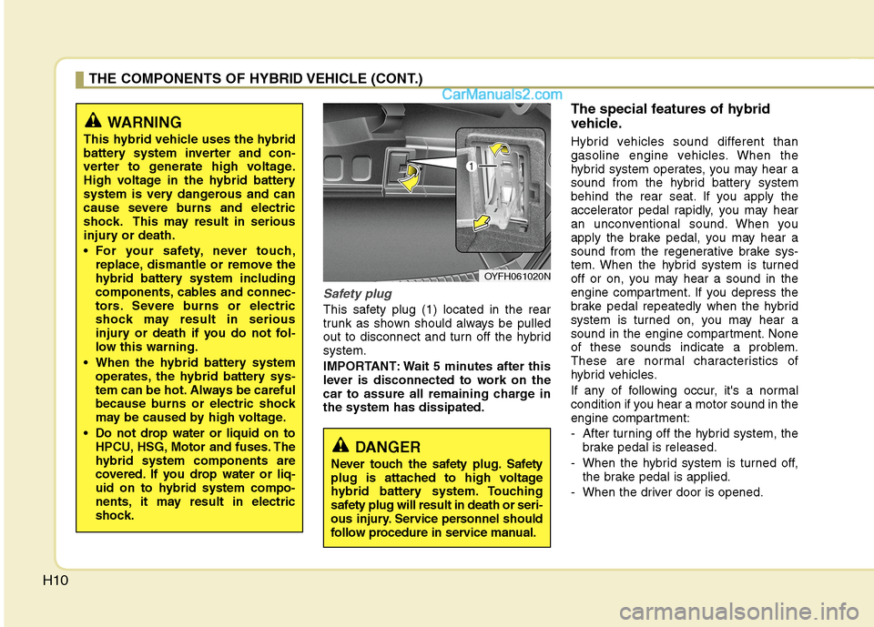
Safety plug
This safety plug (1) located in the rear
trunk as shown should always be pulled
out to disconnect and turn off the hybrid
system.
IMPORTANT: Wait 5 minutes after this
lever is disconnected to work on the
car to assure all remaining charge in
the system has dissipated.
The special features of hybrid
vehicle.
Hybrid vehicles sound different than
gasoline engine vehicles. When the
hybrid system operates, you may hear a
sound from the hybrid battery system
behind the rear seat. If you apply the
accelerator pedal rapidly, you may hear
an unconventional sound. When you
apply the brake pedal, you may hear a
sound from the regenerative brake sys-
tem. When the hybrid system is turned
off or on, you may hear a sound in the
engine compartment. If you depress the
brake pedal repeatedly when the hybrid
system is turned on, you may hear a
sound in the engine compartment. None
of these sounds indicate a problem.
These are normal characteristics of
hybrid vehicles.
If any of following occur, it's a normal
condition if you hear a motor sound in the
engine compartment:
- After turning off the hybrid system, the
brake pedal is released.
- When the hybrid system is turned off,
the brake pedal is applied.
- When the driver door is opened.
THE COMPONENTS OF HYBRID VEHICLE (CONT.)
WARNING
This hybrid vehicle uses the hybrid
battery system inverter and con-
verter to generate high voltage.
High voltage in the hybrid battery
system is very dangerous and can
cause severe burns and electric
shock. This may result in serious
injury or death.
For your safety, never touch,
replace, dismantle or remove the
hybrid battery system including
components, cables and connec-
tors. Severe burns or electric
shock may result in serious
injury or death if you do not fol-
low this warning.
When the hybrid battery system
operates, the hybrid battery sys-
tem can be hot. Always be careful
because burns or electric shock
may be caused by high voltage.
Do not drop water or liquid on to
HPCU, HSG, Motor and fuses. The
hybrid system components are
covered. If you drop water or liq-
uid on to hybrid system compo-
nents, it may result in electric
shock.
DANGER
Never touch the safety plug. Safety
plug is attached to high voltage
hybrid battery system. Touching
safety plug will result in death or seri-
ous injury. Service personnel should
follow procedure in service manual.
OYFH061020N
Page 420 of 425
Index
4I
ECO GUIDE gauge ·······················································4-43
Economical operation ····················································5-28
Electric chromic mirror (ECM) with HomeLink system··4-31
Electric power steering ··················································4-29
Electronic stability control (ESC) ·································5-19
Emergency starting ··························································6-6
Jump starting ·······························································6-6
Push starting ································································6-7
Emergency while driving·················································6-2
Emission control system ················································7-75
Crankcase emission control system ··························7-75
Evaporative emission control system························7-75
Exhaust emission control system ······························7-76
Engine ··············································································8-2
Engine compartment ················································2-4, 7-2
Engine compartment fuse ··············································7-52
Engine coolant ·······························································7-24
Engine number ·································································8-7
Engine oil ·······································································7-22
Engine overheats······························································6-8
Engine start/stop button ···················································5-5
Engine temperature gauge ·············································4-42
Engine will not start·························································6-5
Evaporative emission control system ····························7-75
Exhaust emission control system···································7-76
Explanation of scheduled maintenance items ···············7-19Exterior care···································································7-69
Flat tire (with spare tire) ················································6-14
Changing tires ···························································6-15
Compact spare tire ····················································6-20
Jack and tools ····························································6-14
Removing and storing the spare tire ·························6-15
Flat tire (with tire mobility kit) ·····································6-22
Components of the tire mobility kit ··························6-24
Technical data····························································6-27
Using the tire mobility kit ·········································6-25
Floor mat anchor(s) ······················································4-111
Fluid
Brakes fluid ·······························································7-27
Washer fluid ······························································7-28
Front passenger and rear seat 3-point system with
combination locking retractor ···································3-19
Front seat adjustment ·······················································3-4
Fuel filler lid ··································································4-22
Fuel gauge······································································4-43
Fuel requirements ····························································1-3
Fuse/relay panel description ··········································7-54
Fuses ··············································································7-50
Engine compartment fuse··········································7-52
Fuse/relay panel description······································7-54
Instrument panel fuse ················································7-51
Memory fuse ·····························································7-51
E
F