Page 367 of 403
755
Maintenance
If the headlights or other electrical com-
ponents do not work and the fuses are
OK, check the fuse panel in the engine
compartment. If a fuse is blown, it must
be replaced.
Fuse switch
Always, put the fuse switch at the ON
position.
If you move the switch to the OFF posi-
tion, some items such as audio and digi-
tal clock must be reset and transmitter
(or smart key) may not work properly.
Engine compartment fuse
replacement
1. Turn the ignition switch and all other
switches off.
2. Remove the fuse panel cover by
pressing the tab and pulling up.
3. Check the removed fuse; replace it if it
is blown. To remove or insert the fuse,
use the fuse puller in the engine com-
partment fuse panel.
4. Push in a new fuse of the same rating,
and make sure it fits tightly in the clips.
If it fits loosely, consult an authorized
HYUNDAI dealer.
OHG070018OHG070019
CAUTION
Always place the fuse switch in the
ON position while driving the vehi-
cle.
Page 368 of 403
Maintenance
56 7
Main fuse
If the main fuse is blown, it must be
removed as follows:
1. Turn off the engine.
2. Disconnect the negative battery cable.
3. Remove the nuts shown in the picture
above.
4. Replace the fuse with a new one of the
same rating.
5. Reinstall in the reverse order of
removal.
Multi fuse
If the multi fuse is blown, it must be
removed as follows:
1. Turn off the engine.
2. Disconnect the negative battery cable.
3. Remove the fuse panel in the engine
compartment.
4. Remove the nuts shown in the picture
above.
5. Replace the fuse with a new one of the
same rating.
6. Reinstall in the reverse order of
removal.
✽NOTICE
If the multi fuse is blown, consult an
authorized HYUNDAI dealer.
CAUTION
After checking the fuse panel in the
engine compartment, securely
install the fuse panel cover. If not,
electrical failures may occur from
water contact.
OHG070021OVG079023L
Page 373 of 403
761
Maintenance
No.Fuse ratingSymbol Protected component
MULTI
FUSE
F1 60ASmart Junction Box (Fuse - F20/F25/F28/F35, IPS 1, IPS 2, ARISU-LT 1)
F2 60ASmart Junction Box (Fuse - F26/F29/F32/F36)
F3 40AW/O Smart Key - Ignition Switch
With Smart Key - RLY. 2 (PDM 1 (ACC) Relay), LY. 9 (PDM 2 (IG1) Relay)
F440AESP Control Module, ABS Control Module
F540ARLY. 1 (RR HTD Relay)
F640ARLY. 14 (Blower Relay)
F760ASmart Junction Box (Fuse - F19/F24/F27/F30, IPS 3, IPS 4, ARISU-LT 2)
F880A-
FUSE
F910AA/C Control Module
F1010ARear Combination Lamp (IN) LH/RH, Electro Chromic Mirror , A/V & Navigation Head Unit
F1115ATransaxle Range Switch
F1210APCM
F1310AMultipurpose Check Connector
Engine compartment main fuse panel
Page 380 of 403

Maintenance
68 7
Traffic Change (For Europe)
The low beam light distribution is asym-
metric.
If you go abroad to a country with oppo-
site traffic direction, this asymmetric part
will dazzle oncoming car driver. To pre-
vent dazzle, ECE regulation demand
several technical solutions (ex. automatic
change system, adhesive sheet, down
aiming). This headlamps are designed
not to dazzle opposite drivers. So, you do
not need to change your headlamps in a
country with opposite traffic direction.
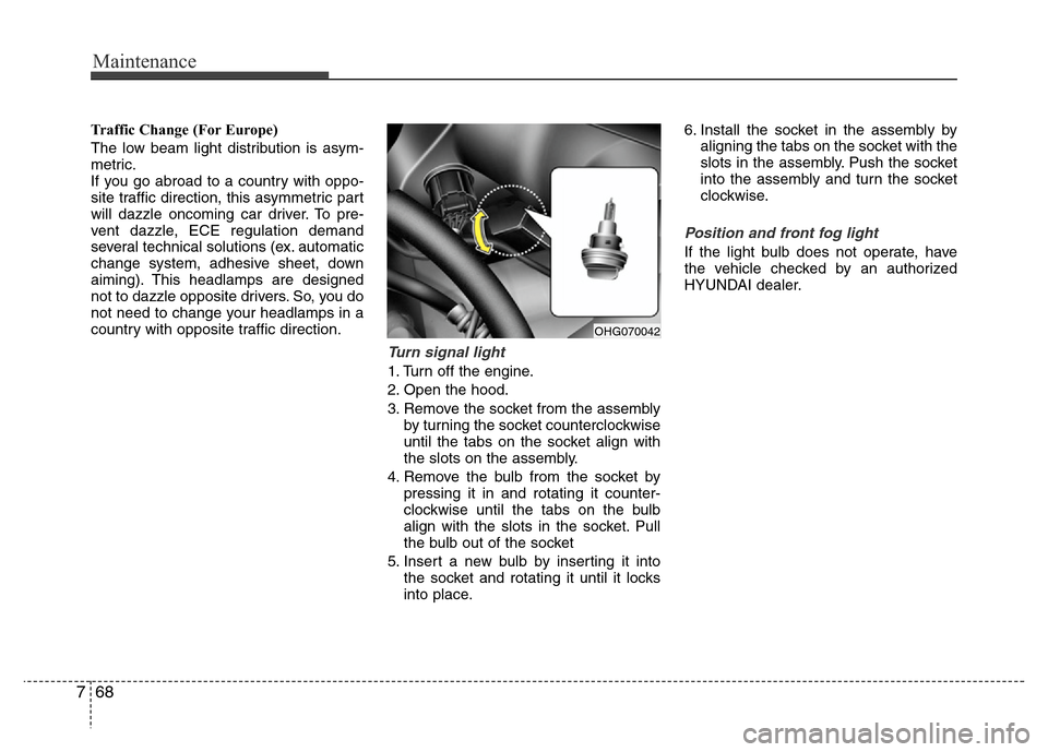
Turn signal light
1. Turn off the engine.
2. Open the hood.
3. Remove the socket from the assembly
by turning the socket counterclockwise
until the tabs on the socket align with
the slots on the assembly.
4. Remove the bulb from the socket by
pressing it in and rotating it counter-
clockwise until the tabs on the bulb
align with the slots in the socket. Pull
the bulb out of the socket
5. Insert a new bulb by inserting it into
the socket and rotating it until it locks
into place.6. Install the socket in the assembly by
aligning the tabs on the socket with the
slots in the assembly. Push the socket
into the assembly and turn the socket
clockwise.
Position and front fog light
If the light bulb does not operate, have
the vehicle checked by an authorized
HYUNDAI dealer.
OHG070042
Page 393 of 403

781
Maintenance
Canister
Fuel vapors generated inside the fuel
tank are absorbed and stored in the
onboard canister. When the engine is
running, the fuel vapors absorbed in the
canister are drawn into the surge tank
through the purge control solenoid valve.
Purge Control Solenoid Valve (PCSV)
The purge control solenoid valve is con-
trolled by the Engine Control Module
(ECM); when the engine coolant temper-
ature is low during idling, the PCSV clos-
es so that evaporated fuel is not taken
into the engine. After the engine warms-
up during ordinary driving, the PCSV
opens to introduce evaporated fuel to the
engine.
3. Exhaust emission control
system
The Exhaust Emission Control System is
a highly effective system which controls
exhaust emissions while maintaining
good vehicle performance.
Vehicle modifications
This vehicle should not be modified.
Modification of your vehicle could affect
its performance, safety or durability and
may even violate governmental safety
and emissions regulations.
In addition, damage or performance
problems resulting from any modification
may not be covered under warranty.
• If you use unauthorized electronic
devices, it may cause the vehicle to
operate abnormally, wire damage, bat-
tery discharge and fire. For your safety,
do not use unauthorized electronic
devices.
Engine exhaust gas precautions (car-
bon monoxide)
• Carbon monoxide can be present with
other exhaust fumes. Therefore, if you
smell exhaust fumes of any kind inside
your vehicle, have it inspected and
repaired immediately. If you ever sus-
pect exhaust fumes are coming into
your vehicle, drive it only with all the
windows fully open. Have your vehicle
checked and repaired immediately.
WARNING- Exhaust
Engine exhaust gases contain car-
bon monoxide (CO). Though color-
less and odorless, it is dangerous
and could be lethal if inhaled.
Follow the instructions on this
page to avoid CO poisoning.
Page 400 of 403

Specifications & Consumer information
6 8
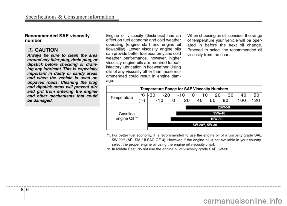
Recommended SAE viscosity
number Engine oil viscosity (thickness) has an
effect on fuel economy and cold weather
operating (engine start and engine oil
flowability). Lower viscosity engine oils
can provide better fuel economy and cold
weather performance, however, higher
viscosity engine oils are required for sat-
isfactory lubrication in hot weather. Using
oils of any viscosity other than those rec-
ommended could result in engine dam-
age.When choosing an oil, consider the range
of temperature your vehicle will be oper-
ated in before the next oil change.
Proceed to select the recommended oil
viscosity from the chart.
CAUTION
Always be sure to clean the area
around any filler plug, drain plug, or
dipstick before checking or drain-
ing any lubricant. This is especially
important in dusty or sandy areas
and when the vehicle is used on
unpaved roads. Cleaning the plug
and dipstick areas will prevent dirt
and grit from entering the engine
and other mechanisms that could
be damaged.
Temperature Range for SAE Viscosity Numbers
Temperature
Gasoline
Engine Oil *
1
°C
(°F)-30 -20 -10 0 10 20 30 40 50
-10 0 20 40 60 80 100 120
*1. For better fuel economy, it is recommended to use the engine oil of a viscosity grade SAE
5W-20*2(API SM / ILSAC GF-4). However, if the engine oil is not available in your country,
select the proper engine oil using the engine oil viscosity chart.
*2. In Middle East, do not use the engine oil of viscosity grade SAE 5W-20.
20W-50
10W-30
15W-40
5W-20*2, 5W-30