Page 180 of 422
You operate the disc player
with the same controls used for the
radio. To select the disc player,
press the CD button. You will see
‘‘CD’’ in the display. To load or play a disc, the ignition
switch must be in the ACCESSORY
(I) or ON (II) position.
CONT INUED
On RT, DX, VP, and Sport models
To Play a Disc
CD Player
175
CD SLOTEJECT BUTTON
TUNE/FOLDER BAR AM/FM
BUTTON
CD BUTTON
PWR BUTTON
SCAN BUTTON
SEEK/SKIP BAR PRESET BARS DISP
BUTTON
RPT
BUTTON
RDM
BUTTON
RT, DX, VP, and Sport models
Do not use discs with adhesive labels.
The label can curl up and cause the
disc to jam in the unit.
12/08/09 16:22:27 31SJC670_182
Features
Page 208 of 422

�´
�µ
�´�µ
�Û�Ý
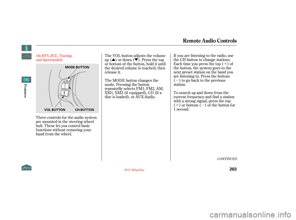
Three controls f or the audio system
are mounted in the steering wheel
hub. These let you control basic
f unctions without removing your
hand f rom the wheel. If you are listening to the radio, use
the CH button to change stations.
Each time you press the top ( ) of
the button, the system goes to the
next preset station on the band you
are listening to. Press the bottom
( ) to go back to the previous
station.
To search up and down from the
current f requency and f ind a station
with a strong signal, press the top
( ) or bottom ( ) of the button for
1 second.
The VOL button adjusts the volume
up ( ) or down ( ). Press the top
or bottom of the button, hold it until
the desired volume is reached, then
release it.
The MODE button changes the
mode. Pressing the button
repeatedly selects FM1, FM2, AM,
XM1, XM2 (if equipped), CD (if a
disc is loaded), or AUX-Audio.
CONT INUED
On RTS, RTL, Touring,
and Sport models
Remote Audio Controls
203
MODE BUTTON
CH BUTTON
VOL BUTTON
12/08/09 16:25:59 31SJC670_210
Features
Page 212 of 422

Press and hold the H (Preset 1) side
of the bar until the hour advances to
the desired time. Press and hold the
M (Preset 2) side of the bar until the
minutes advance to the desired time. To set the time, press the CLOCK
button until you hear a beep. The
displayed time begins to blink. If your vehicle’s battery is
disconnected or goes dead, you may
need to set the clock.You can quickly set the time to the
nearest hour. If the displayed time is
bef ore the half hour, pressing the
clock set button until you hear a
beep, then pressing the R (Preset 3)
side of the bar sets the clock back to
the previous hour.
If the displayed time is after the half
hour, the clock sets f orward to the
beginning of the next hour. Press the clock set button again to
enter the set time. For example:
The navigation system receives
signals f rom the global positioning
system (GPS), and the displayed
time is updated automatically by the
GPS. Ref er to the navigation system
manual f or how to adjust the time.1:06 will reset to 1:00
1:52 will reset to 2:00
On models with navigation system
On models without navigation system
Setting the Clock
207
PRESET BARS
CLOCK BUTTON
CLOCK BUTTON
Model without XM sate llite
radio is shown. PRESET BARS
RTS, RTL, and Touring models without navigation system
RT, DX, VP, and Sport models
12/08/09 16:26:26 31SJC670_214
Features
Page 263 of 422

The maximum load for your
vehicle is:Steps for Determining Correct
Load Limit:
Locate the statement ‘‘The
combined weight of occupants and
cargo should never exceed XXX
kg or XXX lbs.’’ on your vehicle’s
placard.
Determine the combined weight
of the driver and passengers that
will be riding in your vehicle.
Subtract the combined weight of
the driver and passengers f rom
XXX kg or XXX lbs.
These f igures include the total
weight of all occupants, cargo, and
accessories, and the tongue load if
you are towing a trailer.
Label Example See Tire And Loading Inf ormation
label attached to the driver’s
doorjamb. 1.
2.
3.
RT,RTS,DX,VP,CanadianSport
models, and Touring model withoutmoonroof
RTL, U.S. Sport models, and Touringmodel with moonroof
L oad L imits (Payload)
Carrying Cargo
258
1,470 lbs (670 kg) 1,520 lbs (690 kg) Overloading or improper
loading can affect handling and
stability and cause a crash in
which you can be hurt or killed.
Follow all load limits and other
loading guidelines in this
manual.
12/08/09 16:33:31 31SJC670_265
Bef ore Driving
Page 303 of 422

�´
Trailer lights and equipment must
comply with f ederal, state, province/
territory, and local regulations.
Check trailer light requirements f or
the areas where you plan to tow, and
use only equipment designed f or
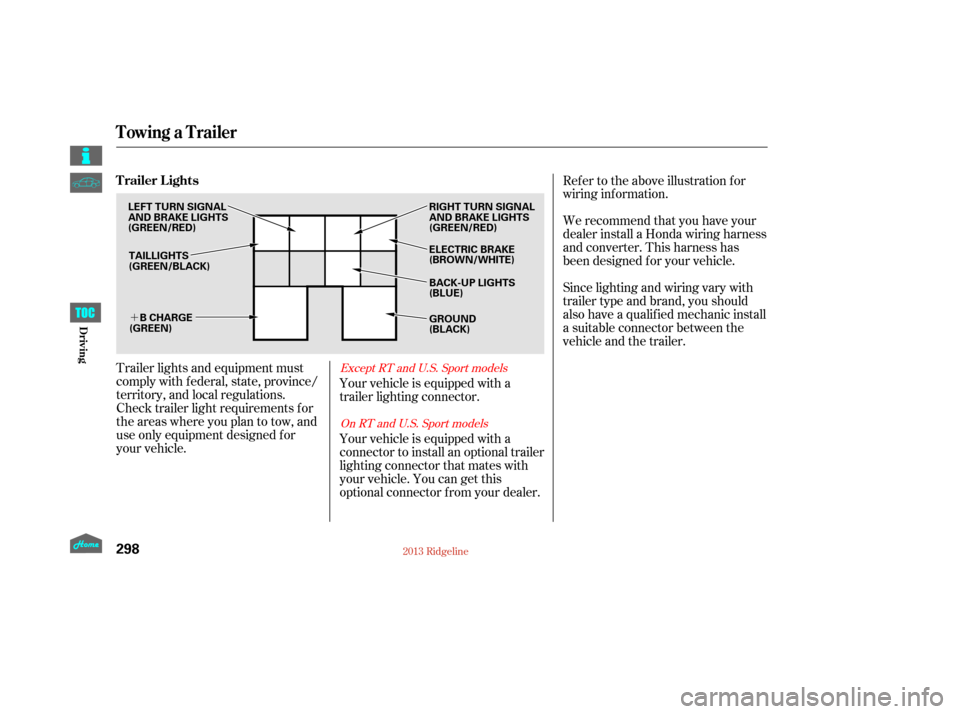
your vehicle.Ref er to the above illustration f or
wiring information.
We recommend that you have your
dealer install a Honda wiring harness
and converter. This harness has
been designed f or your vehicle.
Your vehicle is equipped with a
trailer lighting connector.
Your vehicle is equipped with a
connector to install an optional trailer
lighting connector that mates with
your vehicle. You can get this
optional connector f rom your dealer. Since lighting and wiring vary with
trailer type and brand, you should
also have a qualif ied mechanic install
a suitable connector between the
vehicle and the trailer.Except RT and U.S. Sport models
On RT and U.S. Sport models
Trailer Lights
Towing a Trailer
298
TAILLIGHTS
(GREEN/BLACK) ELECTRIC BRAKE
(BROWN/WHITE) RIGHT TURN SIGNAL
AND BRAKE LIGHTS
(GREEN/RED)
GROUND
(BLACK)
B CHARGE
(GREEN)
LEFT TURN SIGNAL
AND BRAKE LIGHTS
(GREEN/RED)
BACK-UP LIGHTS
(BLUE)
12/08/09 16:38:27 31SJC670_305
Driving
Page 304 of 422
CONT INUED
Insert the connector securely into
the socket.
Hook the retaining tab on the
inner side of the lid against the
retaining tab of the connector to
prevent disconnection during
operation.
Your vehicle has a class 3 trailer
hitch as standard equipment. Make sure the connector and the
socketarefreeof dirt,moisture,
or other f oreign material.
Open the socket lid by pulling it up.
Also see page f or trailer-related
inf ormation.
The 7-pin trailer connector is needed
f or the trailer lights. To connect the
connector:
1.
2.3.
4.
295
Except RT and U.S. Sport models
Towing Equipment
Towing a Trailer
Connect ing t he T railer Connect ors
299
TRAILER HITCH
7-PIN TRAILER CONNECTOR
7-PIN TRAILER CONNECTORLID
RETAINING
TAB
SOCKET RETAINING TAB
12/08/09 16:38:37 31SJC670_306
Driving
Page 305 of 422
�´
Ref er to the above illustrations f or
wiring information.The trailer jumper harness is used to
install the controller f or the electric
trailer brakes. For more inf ormation,
see
on page . Insert the trailer brake f use into the
secondary under-hood f use box (see
page ).
296 379
Except RT and U.S. Sport models Except RT and U.S. Sport models
T railer Connect or Socket s
T railer Jumper Harness
Trailer Brakes T railer Brake Fuse
Towing a Trailer
300
7-PIN TRAILER SOCKET
SMALL
LIGHT
(GREEN)
BACK LIGHT
(YELLOW)
GROUND
(WHITE) GROUND
(BLACK)
ELECTRIC BRAKE
(BROWN/WHITE)
LEFT
TURN/
STOP
(RED) BRAKE
(20A)
(BLUE)
B
CHARGE
(BLACK)
RIGHT
TURN/
STOP
(BROWN)
ELECTRIC
BRAKE
(BLUE) BRAKE LIGHTS
(SKY BLUE)
12/08/09 16:38:45 31SJC670_307
Driving
Page 352 of 422

Never use a puncture-repairing agent
in a f lat tire. If used, you will have to
replace the tire pressure sensor.
Havetheflattirerepairedbyyour
dealer as soon as possible.
The following chart shows the
recommended cold tire pressures
for most normal and high-speed
driving conditions.Your tires have wear indicators
molded into the tread. When the
tread wears down, you will see a 1/2
inch (12.7 mm) wide band across the
tread. This shows there is less than
1/16 inch (1.6 mm) of tread lef t on
the tire.
A tire this worn gives very little
traction on wet roads. You should
replace the tire if you can see three
or more tread wear indicators.
Thecompactsparetirepressureis:
Excessive tread wear. Cuts, splits, or cracks in the side
of the tire. Replace the tire if you
can see f abric or cord. Bumps or bulges in the tread or
side of the tire. Replace the tire if
youfindeitherof theseconditions.
Every time you check inf lation, you
should also examine the tires f or
damage, f oreign objects, and wear.
Youshouldlookfor: For additional inf ormation about
your tires, see page . For convenience, the recommended
tire sizes and cold tire pressures are
on a label on the driver’s doorjamb.
390
Tire Size Cold Tire Pressure
Tire Size Cold Tire PressureFront/Rear:
Front/Rear:
RTL, Touring, and Sport models
RT,RTS,DX,andVPmodels
Recommended Tire Pressures
Tire Inspection
Tires
347
INDICATOR LOCATION MARKS
TREAD WEAR INDICATORS60 psi (420 kPa , 4.2 kgf/cm)
P245/65R17 105T 32 psi (220 kPa , 2.2 kgf/cm
)
P245/60R18 104T 32 psi (220 kPa , 2.2 kgf/cm
)
12/08/09 16:45:08 31SJC670_354
Maint enance