Page 253 of 325
252
uuChecking and Maintaining Wiper BladesuChanging the Rear Wiper Blade Rubber
Maintenance
Changing the Rear Wiper Blade Rubber1.Raise the wiper arm off.
2. Slide the wiper blade out from the wiper
arm while pushing the lock tab.
3. Slide the wiper blade out from its holder by
pulling the tabbed end out.
4. Remove the retainer from wiper blade and
mount it to a new rubber blade.
5. Slide the wiper blade onto the holder.
uMake sure it is engaged correctly, then
install the wiper blade assembly onto the
wiper arm.
1Changing the Rear Wiper Blade Rubber
NOTICE
Avoid dropping the wiper arm; it may damage the rear window.
Tabbed End
Main MenuTable of Contents
Page 263 of 325

262
Maintenance
12 Volt Battery
Checking the 12 Volt BatteryCheck the battery condition monthly. Look at
the test indicator window and check the
terminals for corrosion.
If your vehicle's battery is disconnected or goes dead: • The audio system is disabled.
2 Reactivating the audio system P. 141
• The clock resets.
2 Setting the Clock P. 98
• The navigation system *
is disabled. A PIN code will be required.
2 Refer to the navigation system manual
Charging the 12 Volt Battery
Disconnect both battery cables to prevent damaging your vehicle's electrical system.
Always disconnect the negative (-) cable first, and reconnect it last.
112 Volt Battery
WARNING: Battery post, terminals,
and related accessori es contain lead
and lead compounds. Wash your hands after handling.
The test indicator's color information is on the
battery.
When you find corrosion, clean the battery terminals
by applying a baking powder and water solution. Clean terminals with a damp towel. Cloth/towel dry
the battery. Coat the termina ls with grease to help
prevent future corrosion.
3WARNING
The battery gives off explosive hydrogen
gas during normal operation.
A spark or flame can cause the battery to
explode with enough force to kill or seriously hurt you.
When conducting any battery
maintenance, wear protective clothing and
a face shield, or have a skilled technician do
it.
Test Indicator Window
* Not available on all models
Main MenuTable of Contents
Page 265 of 325
264
Maintenance
Climate Control System Maintenance
Dust and Pollen Filter
The Climate Control system is equipped with a dust and pollen filter that collects
pollen, dust, and other debris in the air. The Maintenance MinderTM
messages will let
you know when to replace the filter.
We recommend that you replace the dust and pollen filter sooner when using your
vehicle in areas with high concentrations of dust.
1Dust and Pollen Filter
If the airflow from the climate control system
deteriorates noticeably, and the windows fog up
easily, the filter may need to be replaced. Please
contact a dealer for replacement.
Main MenuTable of Contents
Page 268 of 325

267
uuCleaninguExterior Care
Continued
Maintenance
Exterior Care
Dust off the vehicle body after you drive.
Regularly inspect your vehicle for scratches on painted surfaces. A scratch on a
painted surface can result in body rust. If you find a scratch, promptly repair it.
Wash the vehicle regularly. Wash more frequently when driving in the following
conditions: •If driving on roads with road salt.
• If driving in coastal areas.
• If tar, soot, bird droppings, insects, or tree sap are stuck to painted surfaces.
Fold in the door mirrors. Make sure to follow the instructions indicated on the automated car wash. • Keep sufficient distance between the cleaning nozzle and the vehicle body.
• Take particular care around the windows. St anding too close may cause water to
enter the vehicle interior. Do not spray water into the engine compartment.
■Washing the Vehicle
■Using an Automated Car Wash
■Using High Pressure Cleaners
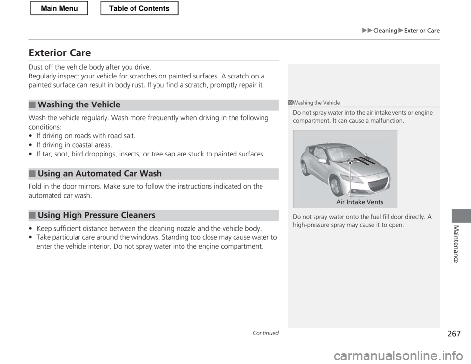
1Washing the Vehicle
Do not spray water into the air intake vents or engine
compartment. It can cause a malfunction.
Do not spray water onto the fuel fill door directly. A
high-pressure spray may cause it to open.
Air Intake Vents
Main MenuTable of Contents
Page 269 of 325

uuCleaninguExterior Care
268
Maintenance
A good coat of automotive body wax helps protect your vehicle’s paint from the
elements. Wax will wear off over time and expose your vehicle’s paint to the
elements, so reapply as necessary.
If you get gasoline, oil, engine coolant, or battery fluid on resin coated parts, they
may be stained or the coating may peel. Promptly wipe it away using a soft cloth and clean water.
Wipe using a glass cleaner.
Aluminum is susceptible to deterio ration caused by salt and other road
contaminants. Use a sponge and mild de tergent to wipe away promptly.
Be careful not to use harsh chemicals (including some commercial wheel cleaners) or
a stiff brush. They can damage the clear coat of the aluminum alloy wheels that
helps keep the aluminum from corroding and tarnishing.
■Applying Wax
■Maintaining the Bumpers and Other Resin Coated Parts
■Cleaning the Window
■Maintaining Aluminum Wheels
1Applying Wax
NOTICE
Chemical solvents and strong cleaners can damage
the paint, metal, and plastic on your vehicle. Wipe up
spills immediately.
1Maintaining the Bumpers and Other Resin Coated Parts
Ask a dealer about the correct coating material when
you want to repair the painted surface of the parts made of resin.
1Cleaning the Window
Wires are mounted to the inside of the rear window.
Wipe along the same direction as the wires with a
soft cloth so as not to damage them.
Main MenuTable of Contents
Page 281 of 325

uuIf a Tire Goes FlatuTemporarily Repairing a Flat Tire
280
Handling the Unexpected
4. Remove the side cover, then pull out the
power plug.
5. Plug in the compressor to the accessory
power socket.
uBe careful not to pinch the cord in a
door or window.
6. Start the engine.
uKeep the engine running while injecting sealant and air.
2 Carbon Monoxide Gas P. 62
7. Press the inflator switch to turn on the compressor.
uThe compressor starts injecting sealant and air into the tire.
8. Continue to add air after the sealant
injection is complete.
9. After the air pressure reaches the required
pressure, turn off the inflator switch.
uTo check the pressure, occasionally turn
off the compressor and read the gauge.
1Injecting Sealant and Air
NOTICE
Do not operate the temporary tire repair kit
compressor for more than 15 minutes. The accessory
power socket and compressor can overheat and become permanently damaged.
There is an accessory power socket in the front
console panel.
2 Accessory Power Socket P. 129
Until the sealant injectio n is complete, the pressure
shown on the pressure gauge will appear higher than
actual. After the sealan t injection is complete the
pressure will drop and then begin to rise again as the
tire is inflated with air. Th is is normal. To accurately
measure the air pressure using the gauge, turn the air
compressor off only after the sealant injection is complete.
See the driver’s doorjamb or the specifications in this
manual for the required air pressure. 2 Specifications P. 306
3WARNING
Running the engine with the vehicle in an
enclosed or even partly enclosed area can
cause a rapid build-up of toxic carbon
monoxide.
Breathing this colorless, odorless gas can
cause unconsciousness and even death. Only run the engi ne to power the air
compressor with the vehicle outdoors.
Inflator Switch
Main MenuTable of Contents
Page 286 of 325

285
uuIf a Tire Goes FlatuTemporarily Repairing a Flat Tire
Handling the Unexpected
7.Remove the side cover, then pull out the
power plug.
8. Plug in the compressor to the accessory power socket.
uBe careful not to pinch the cord in a
door or window.
9. Start the engine.
uKeep the engine running while injecting air.
2 Carbon Monoxide Gas P. 62
10. Press the inflator switch to turn on the compressor.
uThe compressor starts to inject air into
the tire.
11. Inflate the tire to the specified air pressure.
12. Turn off the inflator switch.
uCheck the pressure gauge on the air
compressor.
uIf overinflated, press the pressure relief button.
13. Unplug the compressor from the
accessory power socket.
14. Unscrew the air only hose from the tire
valve stem. Reinstall the valve cap.
15. Press the pressure relief button until the
gauge returns to 0 psi (0 kPa).
16. Repackage and properly stow the kit.
1Inflating An Under-inflated Tire
3WARNING
Running the engine with the vehicle in an
enclosed or even partly enclosed area can
cause a rapid build-up of toxic carbon
monoxide.
Breathing this colorless, odorless gas can
cause unconsciousness and even death. Only run the engi ne to power the air
compressor with the vehicle outdoors.
Side Cover Power Plug
Inflator Switch
Inflator Switch
Pressure
Relief Button
Main MenuTable of Contents
Page 299 of 325

298
uuFusesuFuse Locations
Handling the Unexpected
Located under the driver side dashboard.
Fuse locations are shown on the label on
the back side of the cover.
Locate the fuse in question by the fuse
number and label number.
■Interior Fuse Box
Fuse LabelCover
Fuse Box
■ Circuit protected and fuse rating
Circuit ProtectedAmps
1Back UP15 A
2TPMS *17.5 A
3Driver’s Power Window20 A
4−−
5Back-Up Light10 A
6SRS10 A
7Transmission SOL *210 A
8SRS7.5 A
9Fog Light*20 A
10 A/C 7.5 A
11ABS/VSA ®7.5 A
12 IMA 10 A
13Accessory Power Socket20 A
14 Radio 7.5 A
15Daytime Running Lights7.5 A
16 Rear Wiper 10 A
17Passenger’s Power Window20 A
18 − −
19−−
20 Fuel Pump 15 A
*1:U.S. models only
*2:Automatic transmission (CVT)
*3:Vehicle with halogen bulb low beam headlights
*4:Vehicle with discharge headlights
Circuit ProtectedAmps
21Washer15 A
22 Meter 7.5 A
23Hazard10 A
24 Stop/Horn 10 A
25Audio AMP *20 A
26 LAF 10 A
27Door Lock Main20 A
28 Headlight Main 20 A
29Small Light10 A
30 Main Fan Motor 30 A
31IGPS7.5 A
32 Right Headlight Low
*3
10 A
Right Headlight Low (HID) *4
15 A
33Ignition Coil15 A
34 Left Headlight Low
*3
10 A
Left Headlight High *4
10 A
35Door Lock7.5 A
36 Door Lock 10 A
37ABS FSR/VSA ® FSR30 A
38 − −
* Not available on all models
Main MenuTable of Contents