2013 FORD SUPER DUTY battery
[x] Cancel search: batteryPage 197 of 563

Readiness for Inspection/Maintenance (I/M) Testing
Some state, provincial and local governments may have
Inspection/Maintenance (I/M) programs to inspect the emission control
equipment on your vehicle. Failure to pass this inspection could prevent
you from getting a vehicle registration.
If the service engine soon indicator is on or the bulb does not
work, the vehicle may need to be serviced. SeeOn-board
Diagnostics (OBD-II)in this chapter.
Your vehicle may not pass the I/M test if the service engine soon
indicator is on or not working properly (bulb is burned out), or if the
OBD-II system has determined that some of the emission control systems
have not been properly checked. In this case, the vehicle is considered
not ready for I/M testing.
If the vehicle’s engine or transmission has just been serviced, or the
battery has recently run down or been replaced, the OBD-II system may
indicate that the vehicle is not ready for I/M testing. To determine if the
vehicle is ready for I/M testing, turn the ignition key to the on position
for 15 seconds without cranking the engine. If the service engine soon
indicator blinks eight times, it means that the vehicle is not ready for I/M
testing; if the service engine soon indicator stays on solid, it means that
the vehicle is ready for I/M testing.
The OBD-II system is designed to check the emission control system
during normal driving. A complete check may take several days. If the
vehicle is not ready for I/M testing, the following driving cycle consisting
of mixed city and highway driving may be performed:
15 minutes of steady driving on an expressway or highway followed by
20 minutes of stop-and-go driving with at least four 30-second idle
periods.
Allow the vehicle to sit for at least eight hours without starting the
engine. Then, start the engine and complete the above driving cycle. The
engine must warm up to its normal operating temperature. Once started,
do not turn off the engine until the above driving cycle is complete. If
the vehicle is still not ready for I/M testing, the above driving cycle will
have to be repeated.
196Fuel and Refueling
2013 F-250/350/450/550(f23)
Owners Guide gf, 1st Printing
USA(fus)
Page 204 of 563

Recommended shift speeds
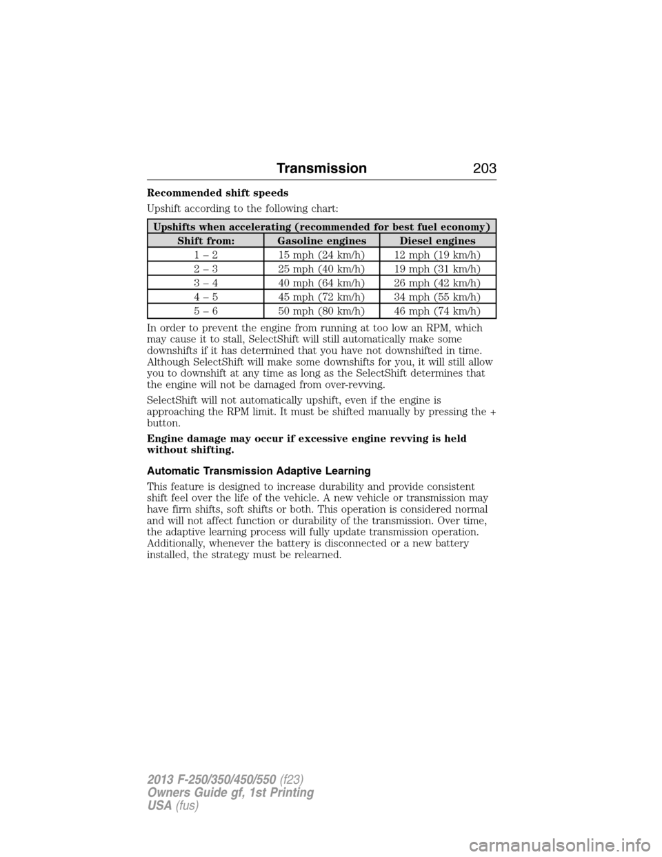
Upshift according to the following chart:
Upshifts when accelerating (recommended for best fuel economy)
Shift from: Gasoline engines Diesel engines
1 – 2 15 mph (24 km/h) 12 mph (19 km/h)
2 – 3 25 mph (40 km/h) 19 mph (31 km/h)
3 – 4 40 mph (64 km/h) 26 mph (42 km/h)
4 – 5 45 mph (72 km/h) 34 mph (55 km/h)
5 – 6 50 mph (80 km/h) 46 mph (74 km/h)
In order to prevent the engine from running at too low an RPM, which
may cause it to stall, SelectShift will still automatically make some
downshifts if it has determined that you have not downshifted in time.
Although SelectShift will make some downshifts for you, it will still allow
you to downshift at any time as long as the SelectShift determines that
the engine will not be damaged from over-revving.
SelectShift will not automatically upshift, even if the engine is
approaching the RPM limit. It must be shifted manually by pressing the +
button.
Engine damage may occur if excessive engine revving is held
without shifting.
Automatic Transmission Adaptive Learning
This feature is designed to increase durability and provide consistent
shift feel over the life of the vehicle. A new vehicle or transmission may
have firm shifts, soft shifts or both. This operation is considered normal
and will not affect function or durability of the transmission. Over time,
the adaptive learning process will fully update transmission operation.
Additionally, whenever the battery is disconnected or a new battery
installed, the strategy must be relearned.
Transmission203
2013 F-250/350/450/550(f23)
Owners Guide gf, 1st Printing
USA(fus)
Page 258 of 563

Explanation of Information Display Warning Messages
Note:Your TBC can be diagnosed by your authorized dealer to determine
exactly which trailer fault has occurred. However, if the fault is with the
trailer this diagnosis isnotcovered under your Ford warranty.
TRAILER BRAKE MODULE FAULT:Displays in response to faults
sensed by the TBC (accompanied by a single chime). If this message is
displayed, please contact your authorized dealer as soon as possible for
diagnosis and repair. The TBC may still function, but performance may
be degraded.
WIRING FAULT ON TRAILER:Displays when a short circuit on the
electric brake output wire has occurred. If theWIRING FAULT ON
TRAILERmessage is displayed and accompanied by a single chime,
with no trailer connected, the problem is with the vehicle wiring between
the TBC to the 7–pin connector at the bumper. If the message is only
displayed with a trailer connected, the problem is related to the trailer
wiring. Consult your trailer dealer for assistance. This can be a short to
ground (i.e., chaffed wire), short to voltage (i.e., pulled pin on trailer
emergency break-away battery) or the trailer brakes may be drawing too
much current.
Points to Remember
Note:Do not attempt removal of the TBC without consulting the
Workshop Manual.Damage to the unit may result.
•Adjust GAIN setting before using the TBC for the first time.
•Adjust GAIN setting (according to procedure above) whenever road,
weather and trailer or vehicle loading conditions change from when
the GAIN was initially set.
•The manual control lever should only be used for proper adjustment
of the GAIN during trailer setup. Misuse, such as application during
trailer sway, could cause instability of trailer or tow vehicle.
•Avoid towing in adverse weather conditions. The TBC does not
provide anti-lock control of the trailer wheels. Trailer wheels can lock
up on slippery surfaces, resulting in reduced stability of trailer and
tow vehicle.
•The TBC is equipped with a feature which reduces output at vehicle
speeds below 11 mph (18 km/h) so trailer and vehicle braking is not
jerky or harsh. This feature is only available when applying the brakes
using the vehicle’s brake pedal, not the TBC.
•The controller interacts with the brake control system and powertrain
control system of the vehicle to provide the best performance on
different road conditions.
Towing257
2013 F-250/350/450/550(f23)
Owners Guide gf, 1st Printing
USA(fus)
Page 272 of 563

ROADSIDE ASSISTANCE
Vehicles Sold in the U.S. : Getting Roadside Assistance
To fully assist you should you have a vehicle concern, Ford Motor
Company offers a complimentary roadside assistance program. This
program is separate from the New Vehicle Limited Warranty. The service
is available:
•24-hours a day, seven days a week
•for the coverage period listed on the Roadside Assistance Card
included in your owner’s manual portfolio.
Roadside assistance will cover:
•a flat tire change with a good spare (except vehicles that have been
supplied with a tire inflation kit).
•battery jump start.
•lock-out assistance (key replacement cost is the customer’s
responsibility).
•fuel delivery – Independent Service Contractors, if not prohibited by
state, local or municipal law shall deliver up to 2.0 gallons (7.5 liters)
of gasoline or 5.0 gallons (18.9 liters) of diesel fuel to a disabled
vehicle. Fuel delivery service is limited to two no-charge occurrences
within a 12-month period.
•winch out – available within 100 feet (30.5 meters) of a paved or
county maintained road, no recoveries.
•towing – Ford and Lincoln eligible vehicles towed to an authorized
dealer within 35 miles (56 kilometers) of the disablement location or
to the nearest authorized dealer. If a member requests to be towed to
an authorized dealer more than 35 miles (56 kilometers) from the
disablement location, the member shall be responsible for any mileage
costs in excess of 35 miles (56 kilometers).
Trailers shall be covered up to $200 if the disabled eligible vehicle
requires service at the nearest authorized dealer. If the trailer is disabled,
but the towing vehicle is operational, the trailer does not qualify for any
roadside services.
Roadside Emergencies271
2013 F-250/350/450/550(f23)
Owners Guide gf, 1st Printing
USA(fus)
Page 274 of 563

HAZARD FLASHER CONTROL
Note:With extended use, the flasher may run down your battery.
The hazard flasher is located on the
steering column, just behind the
steering wheel. The hazard flashers
will operate when the ignition is in
any position or if the key is not in
the ignition.
•Press the flasher control and all
front and rear direction signals
flash.
•Press the flasher control again to turn them off.
Use it when your vehicle is disabled and is creating a safety hazard for
other motorists.
FUEL CUT-OFF SWITCH
WARNING:Failure to inspect and if necessary repair fuel leaks
after a collision may increase the risk of fire and serious injury.
Ford Motor Company recommends that the fuel system be inspected by
an authorized dealer after any collision.
In the event of a moderate to severe collision, this vehicle is equipped
with a fuel pump shut-off feature that stops the flow of fuel to the
engine. Not every impact will cause a shut-off.
Should your vehicle shut off after a collision, you may restart your
vehicle by doing the following:
1. Turn the ignition off.
2. Turn the ignition on.
3. Repeat steps 1 and 2 to re-enable fuel pump.
Note:If your vehicle has the push button start system, press the
stop/start button twice to reactivate the fuel system.
Roadside Emergencies273
2013 F-250/350/450/550(f23)
Owners Guide gf, 1st Printing
USA(fus)
Page 275 of 563

JUMP-STARTING THE VEHICLE
WARNING:The gases around the battery can explode if exposed
to flames, sparks, or lit cigarettes. An explosion could result in
injury or vehicle damage.
WARNING:Batteries contain sulfuric acid which can burn skin,
eyes and clothing, if contacted.
Do not attempt to push-start your automatic transmission vehicle.
Automatic transmissions do not have push-start capability. Attempting to
push-start a vehicle with an automatic transmission may cause
transmission damage.
When the battery is disconnected or a new battery is installed, the
automatic transmission must relearn its shift strategy. As a result, the
transmission may exhibit a combination of firm and soft shifts. This
operation is considered normal and will not affect function or durability
of the transmission. Over time, the adaptive learning process will fully
update transmission operation.
Preparing Your Vehicle
Note:Use only a 12 volt supply to start your vehicle.
Note:Do not disconnect the battery of the disabled vehicle as this could
damage the vehicle’s electrical system.
1. Park the booster vehicle close to the hood of the disabled vehicle
making sure the two vehicles do not touch. Set the parking brake on
both vehicles and stay clear of the engine cooling fan and other moving
parts.
2. Check all battery terminals and remove any excessive corrosion before
you attach the battery cables. Ensure that vent caps are tight and level.
3. Turn the heater fan on in both vehicles to protect from any electrical
surges. Turn all other accessories off.
274Roadside Emergencies
2013 F-250/350/450/550(f23)
Owners Guide gf, 1st Printing
USA(fus)
Page 276 of 563

Connecting the Jumper Cables
WARNING:Do not connect the end of the second cable to the
negative (-) terminal of the battery to be jumped. A spark may
cause an explosion of the gases that surround the battery.
Note:Do not attach the negative (-) cable to fuel lines, engine rocker
covers, the intake manifold or electrical components as grounding points.
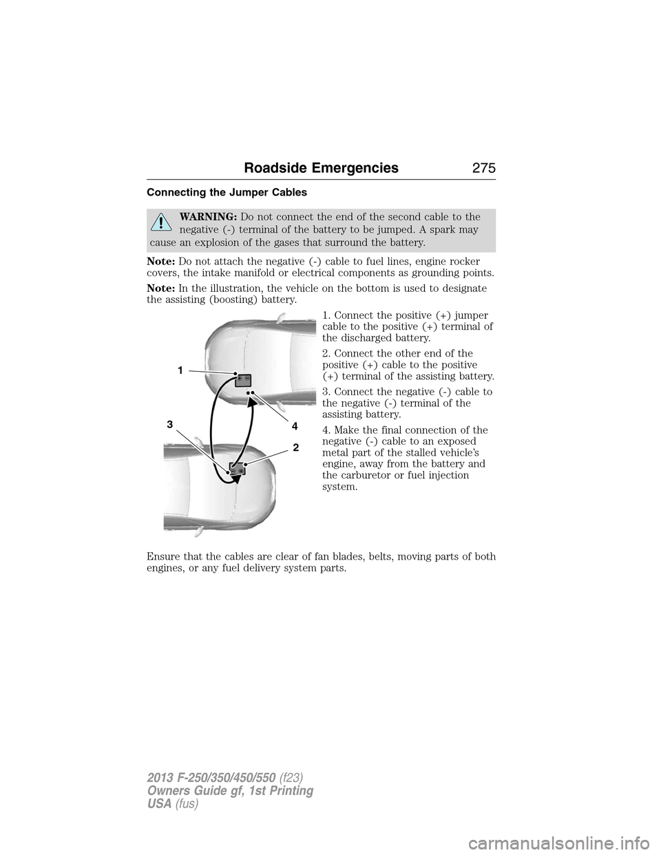
Note:In the illustration, the vehicle on the bottom is used to designate
the assisting (boosting) battery.
1. Connect the positive (+) jumper
cable to the positive (+) terminal of
the discharged battery.
2. Connect the other end of the
positive (+) cable to the positive
(+) terminal of the assisting battery.
3. Connect the negative (-) cable to
the negative (-) terminal of the
assisting battery.
4. Make the final connection of the
negative (-) cable to an exposed
metal part of the stalled vehicle’s
engine, away from the battery and
the carburetor or fuel injection
system.
Ensure that the cables are clear of fan blades, belts, moving parts of both
engines, or any fuel delivery system parts.
4
2
1
3
Roadside Emergencies275
2013 F-250/350/450/550(f23)
Owners Guide gf, 1st Printing
USA(fus)
Page 277 of 563

Jump Starting
1. Start the engine of the booster vehicle and run the engine at a
moderately increased speed.
2. Start the engine of the disabled vehicle.
3. Once the disabled vehicle has been started, run both engines for an
additional three minutes before disconnecting the jumper cables.
Removing the Jumper Cables
Note:In the illustration, the vehicle on the bottom is used to designate
the assisting (boosting) battery.
Remove the jumper cables in the reverse order that they were
connected.
1. Remove the jumper cable from
the ground metal surface.
2. Remove the jumper cable on the
negative (-) terminal of the booster
vehicle’s battery.
3. Remove the jumper cable from
the positive (+) terminal of the
booster vehicle’s battery.
4. Remove the jumper cable from
the positive (+) terminal of the
disabled vehicle’s battery.
After the disabled vehicle has been started and the jumper cables
removed, allow it to idle for several minutes so the engine computer can
relearn its idle conditions.
4
1
3
2
276Roadside Emergencies
2013 F-250/350/450/550(f23)
Owners Guide gf, 1st Printing
USA(fus)