2013 FORD F250 towing
[x] Cancel search: towingPage 212 of 577
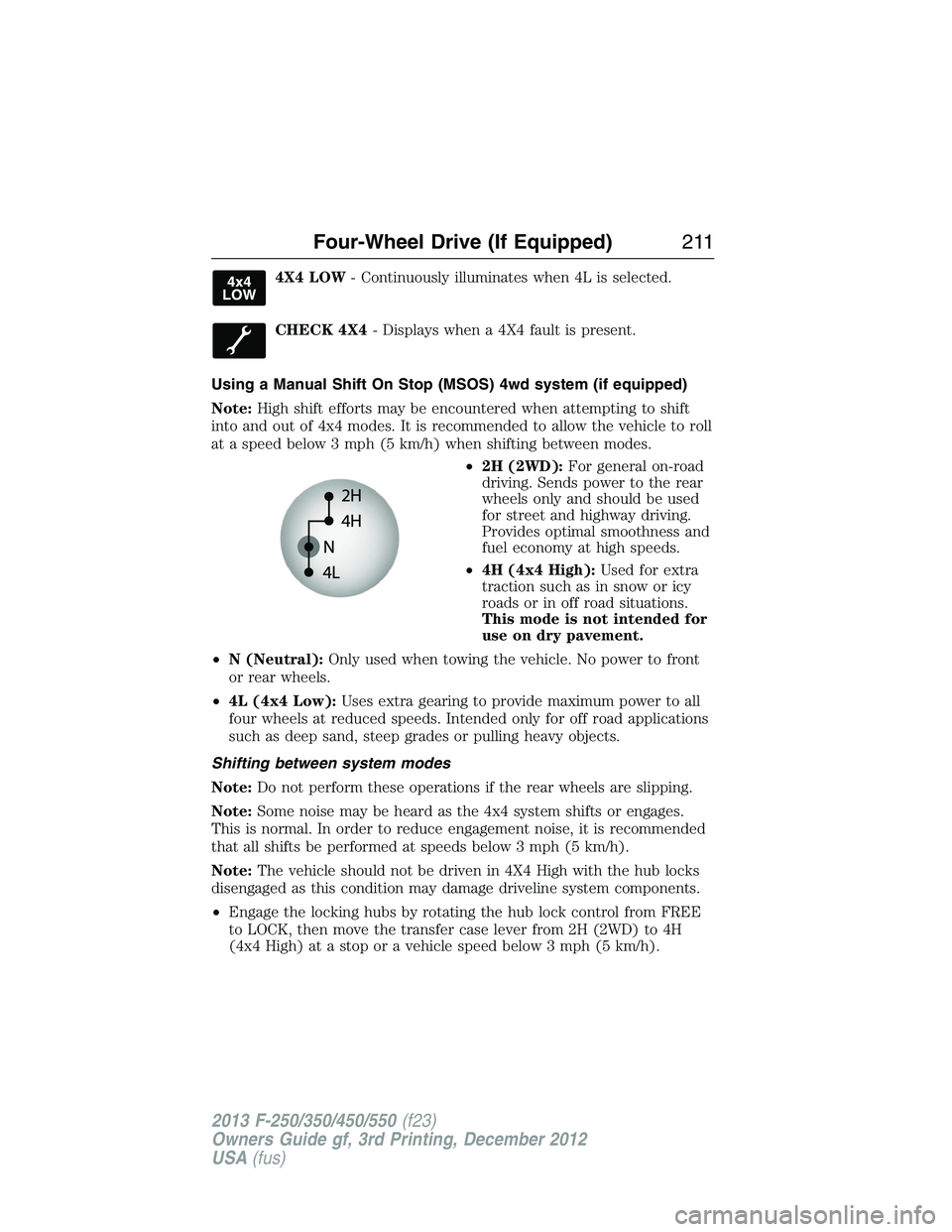
4X4 LOW- Continuously illuminates when 4L is selected.
CHECK 4X4- Displays when a 4X4 fault is present.
Using a Manual Shift On Stop (MSOS) 4wd system (if equipped)
Note:High shift efforts may be encountered when attempting to shift
into and out of 4x4 modes. It is recommended to allow the vehicle to roll
at a speed below 3 mph (5 km/h) when shifting between modes.
•2H (2WD):For general on-road
driving. Sends power to the rear
wheels only and should be used
for street and highway driving.
Provides optimal smoothness and
fuel economy at high speeds.
•4H (4x4 High):Used for extra
traction such as in snow or icy
roads or in off road situations.
This mode is not intended for
use on dry pavement.
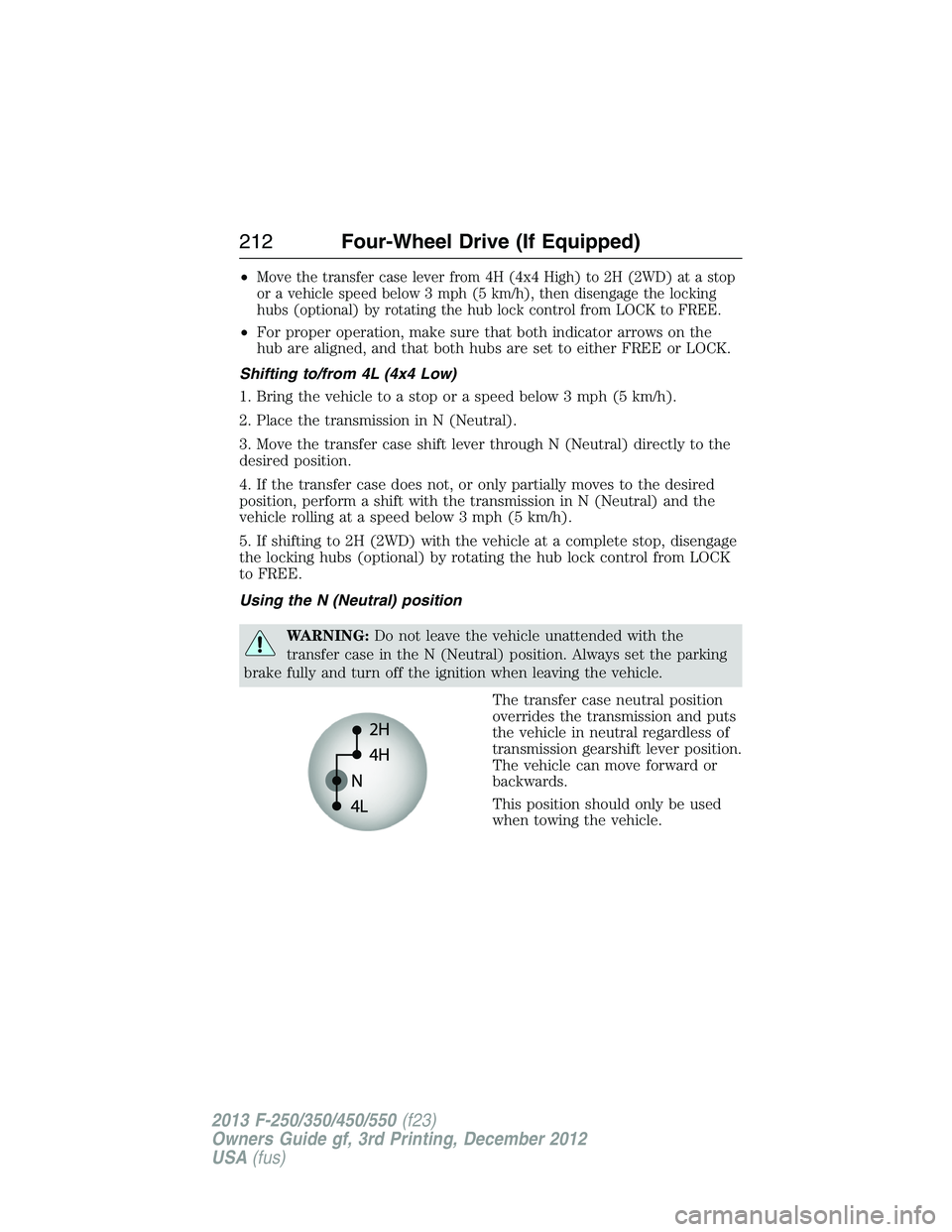
•N (Neutral):Only used when towing the vehicle. No power to front
or rear wheels.
•4L (4x4 Low):Uses extra gearing to provide maximum power to all
four wheels at reduced speeds. Intended only for off road applications
such as deep sand, steep grades or pulling heavy objects.
Shifting between system modes
Note:Do not perform these operations if the rear wheels are slipping.
Note:Some noise may be heard as the 4x4 system shifts or engages.
This is normal. In order to reduce engagement noise, it is recommended
that all shifts be performed at speeds below 3 mph (5 km/h).
Note:The vehicle should not be driven in 4X4 High with the hub locks
disengaged as this condition may damage driveline system components.
•Engage the locking hubs by rotating the hub lock control from FREE
to LOCK, then move the transfer case lever from 2H (2WD) to 4H
(4x4 High) at a stop or a vehicle speed below 3 mph (5 km/h).
Four-Wheel Drive (If Equipped)211
2013 F-250/350/450/550(f23)
Owners Guide gf, 3rd Printing, December 2012
USA(fus)
Page 213 of 577
•Move the transfer case lever from 4H (4x4 High) to 2H (2WD) at a stop
or a vehicle speed below 3 mph (5 km/h), then disengage the locking
hubs (optional) by rotating the hub lock control from LOCK to FREE.
•For proper operation, make sure that both indicator arrows on the
hub are aligned, and that both hubs are set to either FREE or LOCK.
Shifting to/from 4L (4x4 Low)
1. Bring the vehicle to a stop or a speed below 3 mph (5 km/h).
2. Place the transmission in N (Neutral).
3. Move the transfer case shift lever through N (Neutral) directly to the
desired position.
4. If the transfer case does not, or only partially moves to the desired
position, perform a shift with the transmission in N (Neutral) and the
vehicle rolling at a speed below 3 mph (5 km/h).
5. If shifting to 2H (2WD) with the vehicle at a complete stop, disengage
the locking hubs (optional) by rotating the hub lock control from LOCK
to FREE.
Using the N (Neutral) position
WARNING:Do not leave the vehicle unattended with the
transfer case in the N (Neutral) position. Always set the parking
brake fully and turn off the ignition when leaving the vehicle.
The transfer case neutral position
overrides the transmission and puts
the vehicle in neutral regardless of
transmission gearshift lever position.
The vehicle can move forward or
backwards.
This position should only be used
when towing the vehicle.
212Four-Wheel Drive (If Equipped)
2013 F-250/350/450/550(f23)
Owners Guide gf, 3rd Printing, December 2012
USA(fus)
Page 233 of 577

SENSING SYSTEM (IF EQUIPPED)
WARNING:To help avoid personal injury, please read and
understand the limitations of the system as contained in this
section. Sensing is only an aid for some (generally large and fixed)
objects when moving in reverse on a flat surface at parking speeds.
Traffic control systems, inclement weather, air brakes, and external
motors and fans may also affect the function of the sensing system;
this may include reduced performance or a false activation.
WARNING:To help avoid personal injury, always use caution
when in R (Reverse) and when using the sensing system.
WARNING:This system is not designed to prevent contact with
small or moving objects. The system is designed to provide a
warning to assist the driver in detecting large stationary objects to
avoid damaging the vehicle. The system may not detect smaller objects,
particularly those close to the ground.
WARNING:Certain add-on devices such as large trailer hitches,
bike or surfboard racks and any device that may block the normal
detection zone of the system, may create false beeps.
Note:Keep the sensors (located on the bumper/fascia) free from snow,
ice and large accumulations of dirt. If the sensors are covered, the
system’s accuracy can be affected. Do not clean the sensors with sharp
objects.
Note:If your vehicle sustains damage to the bumper/fascia, leaving it
misaligned or bent, the sensing zone may be altered causing inaccurate
measurement of obstacles or false alarms.
Note:If your vehicle is equipped with MyKey®, it is possible to prevent
turning the sensing system off. Refer to theMyKey®chapter.
Note:If your vehicle is equipped with a fully integrated electronic
trailer brake controller (TBC) and a trailer with electric trailer brakes is
connected to your vehicle, the RSS will be disabled. When the vehicle is
shifted into reverse, the message center display will remain in the Rear
Park Aid Off selection. For more information on the TBC, refer to the
Towingchapter.
232Parking Aids
2013 F-250/350/450/550(f23)
Owners Guide gf, 3rd Printing, December 2012
USA(fus)
Page 236 of 577
Using the Rear View Camera System
The rear view camera system displays what is behind your vehicle when
you place the transmission in R (Reverse). The system uses two types of
guides to help you see what is behind your vehicle:
1. Fixed guidelines: Show the actual path the vehicle is moving in while
reversing in a straight line, which can be helpful when backing into a
parking space or aligning the vehicle with another object behind the
vehicle.
2. Centerline: Helps align the center of the vehicle with an object
(i.e. a trailer).
Note:If the image comes on while the transmission is not in R
(Reverse), have the system inspected by your authorized dealer.
Note:When towing, the camera only sees what is being towed behind
the vehicle. This might not provide adequate coverage as it usually
provides in normal operation and some objects might not be seen.
In some vehicles, the guidelines may disappear once the trailer tow
connector is engaged.
Note:The default setting for the camera delay is off. Press the Settings
button found on the navigation screen (if equipped) to set the camera
delay feature to on or off.
Note:The camera may not operate correctly under the following
conditions:
•Nighttime or dark areas if one or both reverse lamps are not
operating.
•The camera’s view is obstructed by mud, water or debris. Clean the
lens with a soft, lint-free cloth and non-abrasive cleaner.
•The rear of the vehicle is hit or damaged, causing the camera to
become misaligned.
Parking Aids235
2013 F-250/350/450/550(f23)
Owners Guide gf, 3rd Printing, December 2012
USA(fus)
Page 244 of 577
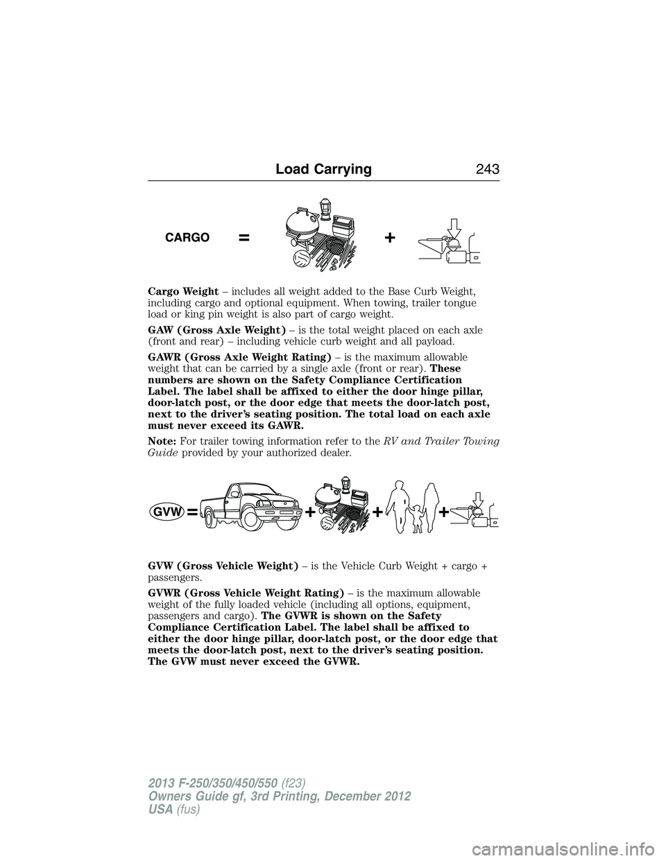
Cargo Weight– includes all weight added to the Base Curb Weight,
including cargo and optional equipment. When towing, trailer tongue
load or king pin weight is also part of cargo weight.
GAW (Gross Axle Weight)– is the total weight placed on each axle
(front and rear) – including vehicle curb weight and all payload.
GAWR (Gross Axle Weight Rating)– is the maximum allowable
weight that can be carried by a single axle (front or rear).These
numbers are shown on the Safety Compliance Certification
Label. The label shall be affixed to either the door hinge pillar,
door-latch post, or the door edge that meets the door-latch post,
next to the driver’s seating position. The total load on each axle
must never exceed its GAWR.
Note:For trailer towing information refer to theRV and Trailer Towing
Guideprovided by your authorized dealer.
GVW (Gross Vehicle Weight)– is the Vehicle Curb Weight + cargo +
passengers.
GVWR (Gross Vehicle Weight Rating)– is the maximum allowable
weight of the fully loaded vehicle (including all options, equipment,
passengers and cargo).The GVWR is shown on the Safety
Compliance Certification Label. The label shall be affixed to
either the door hinge pillar, door-latch post, or the door edge that
meets the door-latch post, next to the driver’s seating position.
The GVW must never exceed the GVWR.
Load Carrying243
2013 F-250/350/450/550(f23)
Owners Guide gf, 3rd Printing, December 2012
USA(fus)
Page 246 of 577
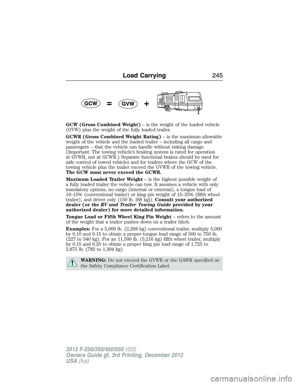
GCW (Gross Combined Weight)– is the weight of the loaded vehicle
(GVW) plus the weight of the fully loaded trailer.
GCWR (Gross Combined Weight Rating)– is the maximum allowable
weight of the vehicle and the loaded trailer – including all cargo and
passengers – that the vehicle can handle without risking damage.
(Important: The towing vehicle’s braking system is rated for operation
at GVWR, not at GCWR.) Separate functional brakes should be used for
safe control of towed vehicles and for trailers where the GCW of the
towing vehicle plus the trailer exceed the GVWR of the towing vehicle.
The GCW must never exceed the GCWR.
Maximum Loaded Trailer Weight– is the highest possible weight of
a fully loaded trailer the vehicle can tow. It assumes a vehicle with only
mandatory options, no cargo (internal or external), a tongue load of
10–15% (conventional trailer) or king pin weight of 15–25% (fifth wheel
trailer), and driver only (150 lb. [68 kg]).Consult your authorized
dealer (or theRV and Trailer Towing Guideprovided by your
authorized dealer) for more detailed information.
Tongue Load or Fifth Wheel King Pin Weight– refers to the amount
of the weight that a trailer pushes down on a trailer hitch.
Examples:For a 5,000 lb. (2,268 kg) conventional trailer, multiply 5,000
by 0.10 and 0.15 to obtain a proper tongue load range of 500 to 750 lb.
(227 to 340 kg). For an 11,500 lb. (5,216 kg) fifth wheel trailer, multiply
by 0.15 and 0.25 to obtain a proper king pin load range of 1,725 to
2,875 lb. (782 to 1,304 kg)
WARNING:Do not exceed the GVWR or the GAWR specified on
the Safety Compliance Certification Label.
Load Carrying245
2013 F-250/350/450/550(f23)
Owners Guide gf, 3rd Printing, December 2012
USA(fus)
Page 247 of 577
WARNING:Do not use replacement tires with lower load
carrying capacities than the original tires because they may lower
the vehicle’s GVWR and GAWR limitations. Replacement tires with a
higher limit than the original tires do not increase the GVWR and
GAWR limitations.
WARNING:Exceeding any vehicle weight rating limitation could
result in serious damage to the vehicle and/or personal injury.
Steps for determining the correct load limit:
1. Locate the statement “The combined weight of occupants and cargo
should never exceed XXX kg or XXX lb.” on your vehicle’s placard.
2. Determine the combined weight of the driver and passengers that will
be riding in your vehicle.
3. Subtract the combined weight of the driver and passengers from
XXX kg or XXX lb.
4. The resulting figure equals the available amount of cargo and luggage
load capacity. For example, if the “XXX” amount equals 1,400 lb. and
there will be five 150 lb. passengers in your vehicle, the amount of
available cargo and luggage load capacity is 650 lb. (1400-750 (5 x 150)
= 650 lb.).
5. Determine the combined weight of luggage and cargo being loaded on
the vehicle. That weight may not safely exceed the available cargo and
luggage load capacity calculated in Step 4.
6. If your vehicle will be towing a trailer, load from your trailer will be
transferred to your vehicle. Consult this manual to determine how this
reduces the available cargo and luggage load capacity of your vehicle.
The following gives you a few examples on how to calculate the available
amount of cargo and luggage load capacity:
•
Suppose your vehicle has a 1400 lb. (635 kg) cargo and luggage
capacity. You decide to go golfing. Is there enough load capacity to carry
you, 4 of your friends and all the golf bags? You and four friends average
220 lb. (99 kg) each and the golf bags weigh approximately 30 lb.
(13.5 kg) each. The calculation would be: 1400 - (5 x 220) - (5 x 30) =
1400 - 1100 - 150 = 150 lb. Yes, you have enough load capacity in your
vehicle to transport four friends and your golf bags. In metric units, the
calculation would be: 635 kg - (5 x 99 kg) - (5 x 13.5 kg) = 635 - 495 -
67.5 = 72.5 kg.
246Load Carrying
2013 F-250/350/450/550(f23)
Owners Guide gf, 3rd Printing, December 2012
USA(fus)
Page 254 of 577

TOWING A TRAILER
WARNING:Do not exceed the GVWR or the GAWR specified on
the certification label.
WARNING:Towing trailers beyond the maximum recommended
gross trailer weight exceeds the limit of your vehicle and could
result in engine damage, transmission damage, structural damage, loss
of vehicle control, vehicle rollover and personal injury.
Note:For information on electrical items such as fuses or relays, see the
Fuseschapter.
Your vehicle’s load capacity designation is by weight, not by volume, so
you cannot necessarily use all available space when loading a vehicle.
Towing a trailer places an extra load on your vehicle’s engine,
transmission, axle, brakes, tires and suspension. Inspect these
components periodically during, and after, any towing operation.
Load Placement
To help minimize how trailer movement affects your vehicle when
driving:
•Load the heaviest items closest to the trailer floor.
•Load the heaviest items centered between the left and right side
trailer tires.
•Load the heaviest items above the trailer axles or just slightly forward
toward the trailer tongue. Do not allow the final trailer tongue weight
to go above or below 10–15% of the loaded trailer weight.
•Select a tow bar with the correct rise or drop. When both the loaded
vehicle and trailer are connected, the trailer frame should be level, or
slightly angled down toward your vehicle, when viewed from the side.
When driving with a trailer or payload, a slight takeoff vibration or
shudder may be present due to the increased payload weight. You can
find more information about proper trailer loading and setting your
vehicle up for towing underLoad limitin theLoad Carryingchapter
and in theRV & Trailer Towing Guide,available at an authorized
dealer.
Towing253
2013 F-250/350/450/550(f23)
Owners Guide gf, 3rd Printing, December 2012
USA(fus)