Page 321 of 577
3. Run the engine until it reaches normal operating temperature.
4. Allow the engine to idle for at least one minute.
5. Turn the A/C on and allow the engine to idle for at least one minute.
6. Release the parking brake. With your foot on the brake pedal and with
the A/C on, put the vehicle in D (Drive) and allow the engine to idle for
at least one minute.
Note:If you do not allow the engine to relearn its idle trim, the idle
quality of your vehicle may be adversely affected until the idle trim is
eventually relearned.
7. Drive the vehicle to complete the relearning process.
•The vehicle may need to be driven 10 miles (16 kilometers) or more
to relearn the idle and fuel trim strategy along with the ethanol
content for flexible fuel vehicles.
•For flexible fuel vehicles, if you are operating on E85, you may
experience poor starts or an inability to start the engine and
driveability problems until the fuel trim and ethanol content
have been relearned.
If the battery has been disconnected or a new battery has been installed,
the clock and radio settings must be reset once the battery is reconnected.
•Always dispose of automotive
batteries in a responsible manner.
Follow your local authorized
standards for disposal. Call your
local authorized recycling center
to find out more about recycling
automotive batteries.
L
E
A
D
RETURN
RECYCLE
320Maintenance
2013 F-250/350/450/550(f23)
Owners Guide gf, 3rd Printing, December 2012
USA(fus)
Page 327 of 577
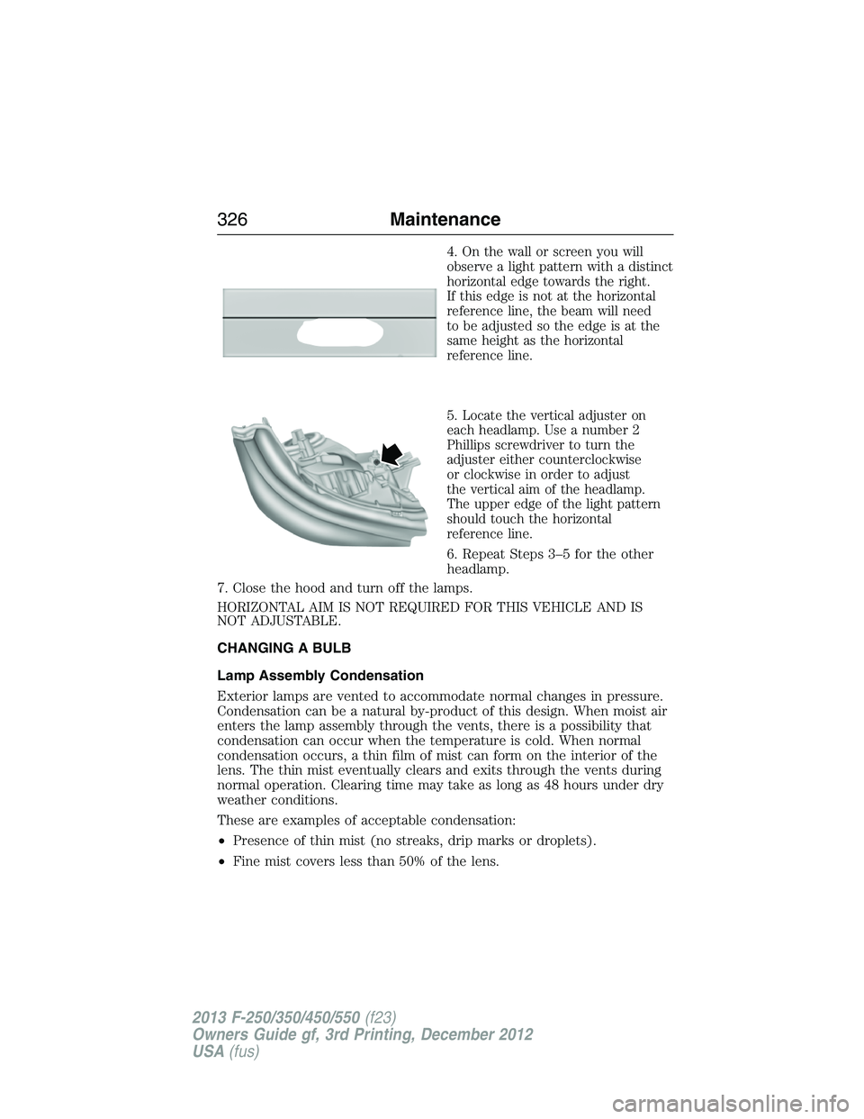
4.On the wall or screen you will
observe a light pattern with a distinct
horizontal edge towards the right.
If this edge is not at the horizontal
reference line, the beam will need
to be adjusted so the edge is at the
same height as the horizontal
reference line.
5.Locate the vertical adjuster on
each headlamp. Use a number 2
Phillips screwdriver to turn the
adjuster either counterclockwise
or clockwise in order to adjust
the vertical aim of the headlamp.
The upper edge of the light pattern
should touch the horizontal
reference line.
6. Repeat Steps 3–5 for the other
headlamp.
7. Close the hood and turn off the lamps.
HORIZONTAL AIM IS NOT REQUIRED FOR THIS VEHICLE AND IS
NOT ADJUSTABLE.
CHANGING A BULB
Lamp Assembly Condensation
Exterior lamps are vented to accommodate normal changes in pressure.
Condensation can be a natural by-product of this design. When moist air
enters the lamp assembly through the vents, there is a possibility that
condensation can occur when the temperature is cold. When normal
condensation occurs, a thin film of mist can form on the interior of the
lens. The thin mist eventually clears and exits through the vents during
normal operation. Clearing time may take as long as 48 hours under dry
weather conditions.
These are examples of acceptable condensation:
•Presence of thin mist (no streaks, drip marks or droplets).
•Fine mist covers less than 50% of the lens.
326Maintenance
2013 F-250/350/450/550(f23)
Owners Guide gf, 3rd Printing, December 2012
USA(fus)
Page 329 of 577
10. For the headlamp bulb,
remove the bulb by turning it
counterclockwise and pulling it
straight out.
11. For the park or turn lamp bulb,
remove the bulb by turning it
counterclockwise and pulling it
straight out.
WARNING:Handle a halogen headlamp bulb carefully and keep
out of children’s reach. Grasp the bulb only by its plastic base
and do not touch the glass. The oil from your hand could cause the
bulb to break the next time the headlamps are operated.
Install the new bulb(s) in reverse order.
328Maintenance
2013 F-250/350/450/550(f23)
Owners Guide gf, 3rd Printing, December 2012
USA(fus)
Page 330 of 577
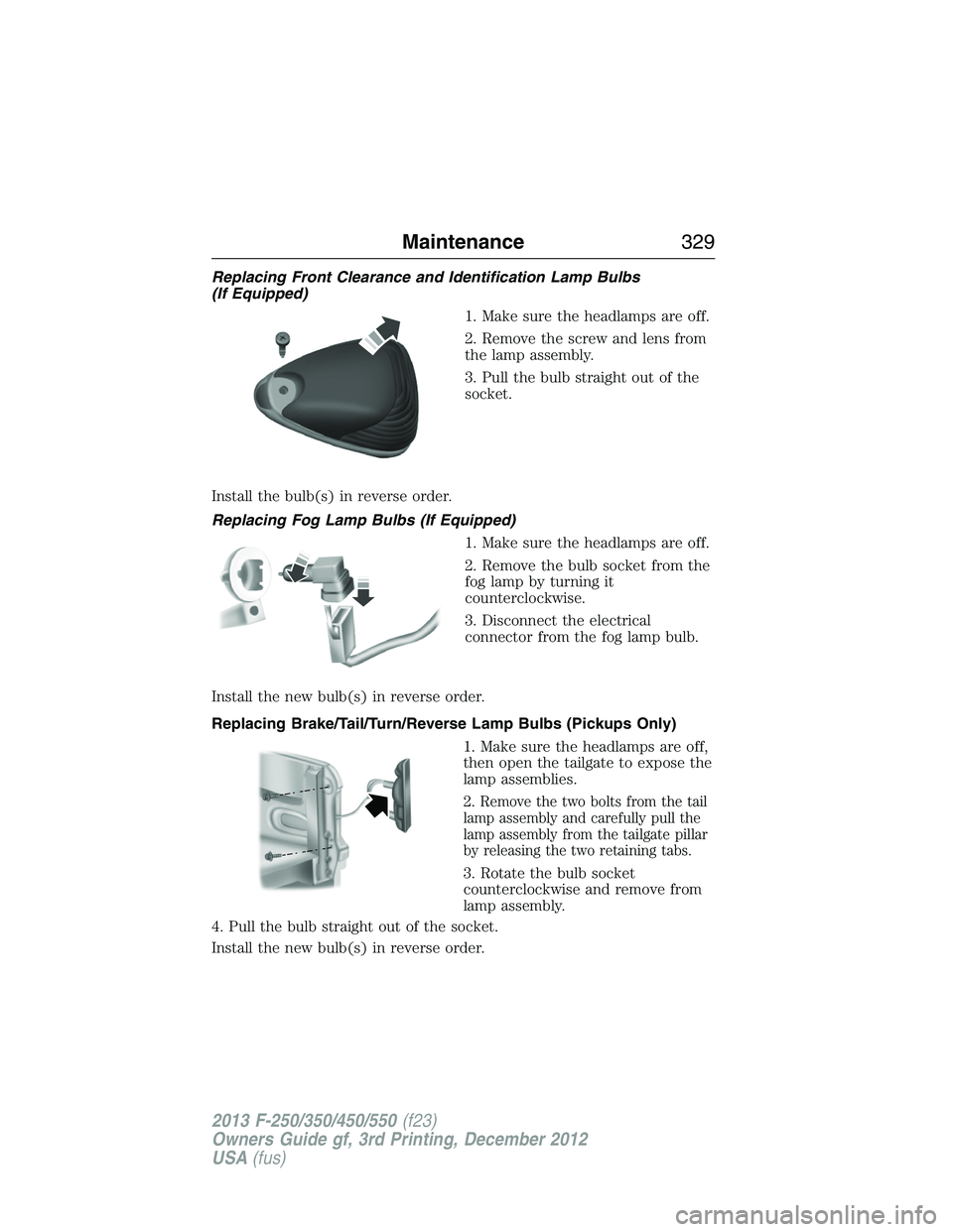
Replacing Front Clearance and Identification Lamp Bulbs
(If Equipped)
1. Make sure the headlamps are off.
2. Remove the screw and lens from
the lamp assembly.
3. Pull the bulb straight out of the
socket.
Install the bulb(s) in reverse order.
Replacing Fog Lamp Bulbs (If Equipped)
1. Make sure the headlamps are off.
2. Remove the bulb socket from the
fog lamp by turning it
counterclockwise.
3. Disconnect the electrical
connector from the fog lamp bulb.
Install the new bulb(s) in reverse order.
Replacing Brake/Tail/Turn/Reverse Lamp Bulbs (Pickups Only)
1. Make sure the headlamps are off,
then open the tailgate to expose the
lamp assemblies.
2.
Remove the two bolts from the tail
lamp assembly and carefully pull the
lamp assembly from the tailgate pillar
by releasing the two retaining tabs.
3. Rotate the bulb socket
counterclockwise and remove from
lamp assembly.
4. Pull the bulb straight out of the socket.
Install the new bulb(s) in reverse order.
Maintenance329
2013 F-250/350/450/550(f23)
Owners Guide gf, 3rd Printing, December 2012
USA(fus)
Page 331 of 577
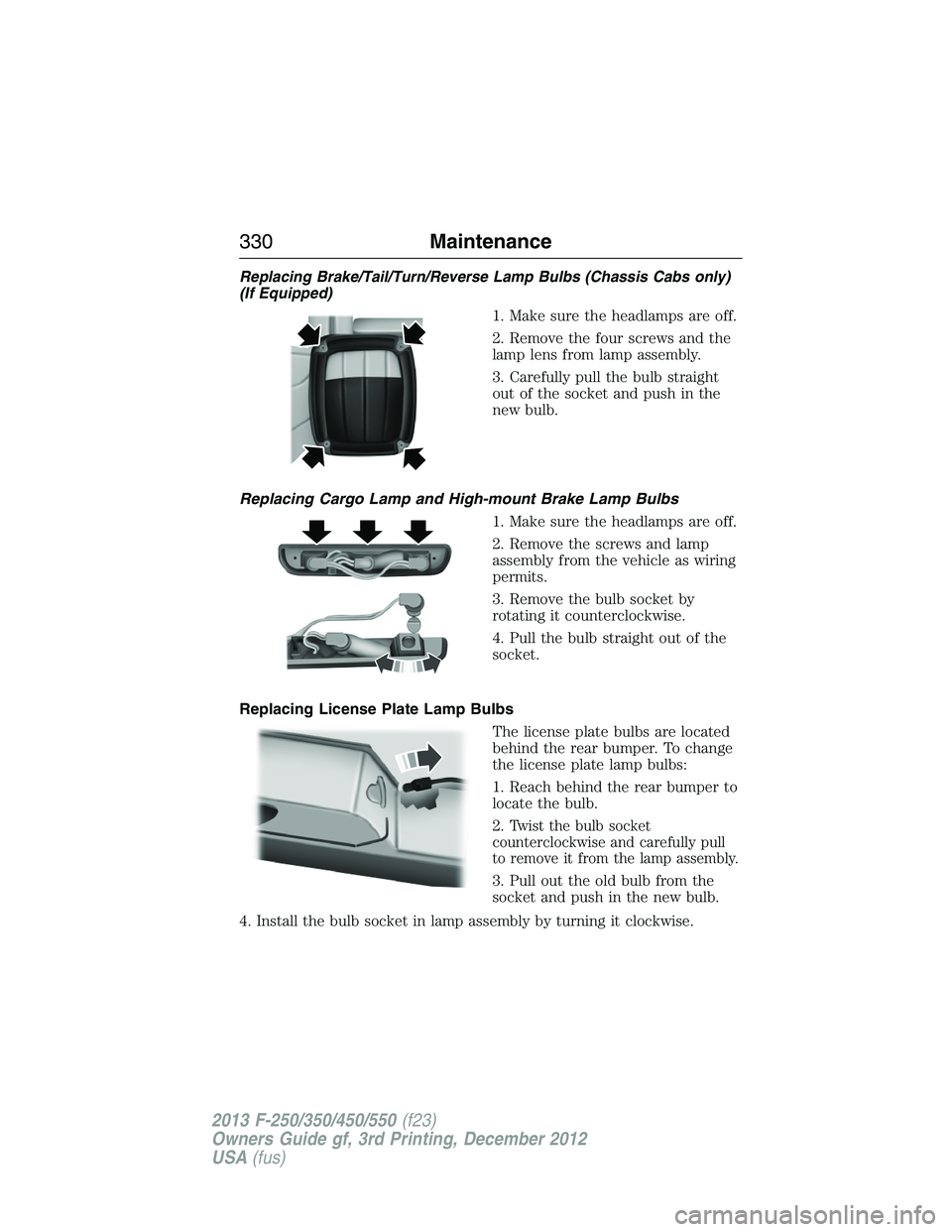
Replacing Brake/Tail/Turn/Reverse Lamp Bulbs (Chassis Cabs only)
(If Equipped)
1. Make sure the headlamps are off.
2. Remove the four screws and the
lamp lens from lamp assembly.
3. Carefully pull the bulb straight
out of the socket and push in the
new bulb.
Replacing Cargo Lamp and High-mount Brake Lamp Bulbs
1. Make sure the headlamps are off.
2. Remove the screws and lamp
assembly from the vehicle as wiring
permits.
3. Remove the bulb socket by
rotating it counterclockwise.
4. Pull the bulb straight out of the
socket.
Replacing License Plate Lamp Bulbs
The license plate bulbs are located
behind the rear bumper. To change
the license plate lamp bulbs:
1. Reach behind the rear bumper to
locate the bulb.
2.
Twist the bulb socket
counterclockwise and carefully pull
to remove it from the lamp assembly.
3. Pull out the old bulb from the
socket and push in the new bulb.
4. Install the bulb socket in lamp assembly by turning it clockwise.
330Maintenance
2013 F-250/350/450/550(f23)
Owners Guide gf, 3rd Printing, December 2012
USA(fus)
Page 371 of 577

Performing the System Reset Procedure
Read the entire procedure before attempting.
1. Drive the vehicle above 20 mph (32 km/h) for at least two minutes
and then park in a safe location where you can easily get to all four tires
and have access to an air pump.
2. Place the ignition in the off position and keep the key in the ignition.
3. Cycle the ignition to the on position with the engine off.
4. Turn the hazard flashers on then off three times. This must be
accomplished within 10 seconds.
If the reset mode has been entered successfully, the horn will sound
once, the system indicator will flash and a message is shown in the
information display (if equipped). If this does not occur, please try again
starting at Step 2.
If after repeated attempts to enter the reset mode, the horn does not
sound, the system indicator does not flash and no message is shown in the
information display (if equipped), seek service from your authorized dealer.
5.Note:Train the tire pressure monitoring system sensors in the tires
using the following system reset sequence starting with the left front tire
in the following clockwise order:
•Left front (Driver’s side front tire)
•Right front (Passenger’s side front tire)
•Right rear (Passenger’s side rear tire)
•Left rear (Driver’s side rear tire)
6. Remove the valve cap from the valve stem on the left front tire;
decrease the air pressure until the horn sounds.
Note:The single horn chirp confirms that the sensor identification code
has been learned by the module for this position. If a double horn is
heard, the reset procedure was unsuccessful, and must be repeated.
7. Remove the valve cap from the valve stem on the right front tire;
decrease the air pressure until the horn sounds.
8. Remove the valve cap from the valve stem on the right rear tire;
decrease the air pressure until the horn sounds.
9. Remove the valve cap from the valve stem on the left rear tire;
decrease the air pressure until the horn sounds.
Training is complete after the horn sounds for the last tire trained
(driver’s side rear tire), the system indicator stops flashing, and a
message is shown in the information display (if equipped).
370Wheels and Tires
2013 F-250/350/450/550(f23)
Owners Guide gf, 3rd Printing, December 2012
USA(fus)
Page 376 of 577
•Note:For vehicles equipped with
dual rear wheels, insert the lug
wrench extension into the lug
wrench to reach the lug nuts.
2. Attach the spare tire lock key
(A) to the jack handle (B).
3. Fully insert the jack handle (with
one extension) through the bumper
hole and into the guide tube. The
key and lock will engage with a
slight push and counterclockwise
turn. Some resistance will be felt
when turning the jack handle
assembly.
4. Turn the handle counterclockwise and lower the spare tire until you
can slide the tire rearward and the cable is slack.
5. Remove the retainer through the center of the wheel.
Note:If equipped with a tether, perform the following steps:
AB
AB
Wheels and Tires375
2013 F-250/350/450/550(f23)
Owners Guide gf, 3rd Printing, December 2012
USA(fus)
Page 378 of 577
WARNING:Always use the jack provided as original equipment
with your vehicle. If using a jack other than the one provided as
original equipment with your vehicle, make sure the jack capacity is
adequate for the vehicle weight, including any vehicle cargo or
modifications.
Note:Passengers should not remain in the vehicle when the vehicle is
being jacked.
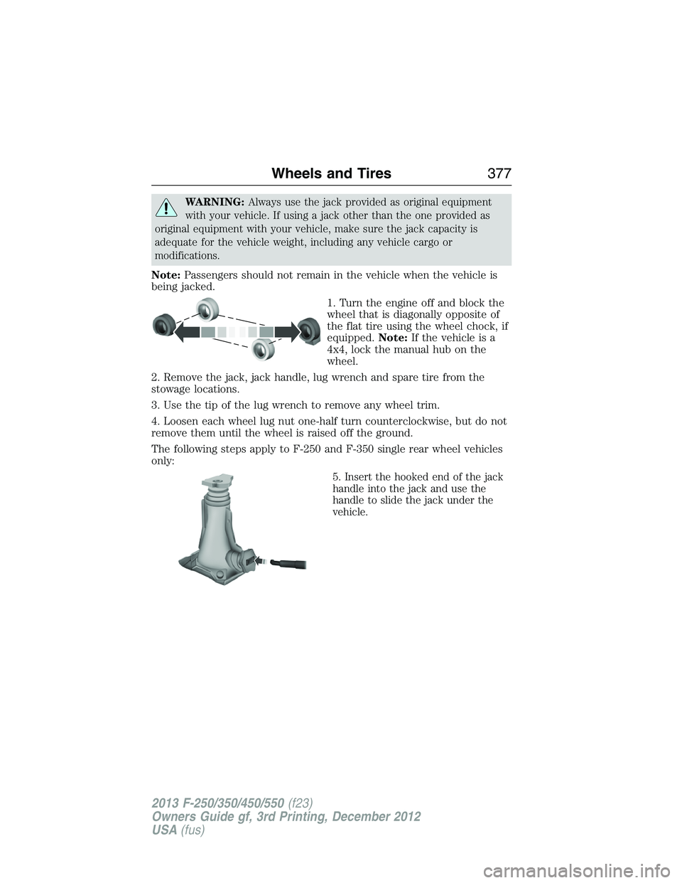
1. Turn the engine off and block the
wheel that is diagonally opposite of
the flat tire using the wheel chock, if
equipped.Note:If the vehicle is a
4x4, lock the manual hub on the
wheel.
2. Remove the jack, jack handle, lug wrench and spare tire from the
stowage locations.
3. Use the tip of the lug wrench to remove any wheel trim.
4. Loosen each wheel lug nut one-half turn counterclockwise, but do not
remove them until the wheel is raised off the ground.
The following steps apply to F-250 and F-350 single rear wheel vehicles
only:
5. Insert the hooked end of the jack
handle into the jack and use the
handle to slide the jack under the
vehicle.
Wheels and Tires377
2013 F-250/350/450/550(f23)
Owners Guide gf, 3rd Printing, December 2012
USA(fus)