Page 181 of 577

Your vehicle may have more than
one power point, located:
•on the back of the center console
•on the instrument panel.
Your power points are not designed for the following electric appliances
and may prevent the appliances from working properly:
•Cathode ray tube type televisions
•Motor loads, such as vacuum cleaners, electric saws and other electric
power tools, compressor-driven refrigerators, etc.
•Measuring devices, which process precise data, such as medical
equipment, measuring equipment, etc.
•Other appliances requiring an extremely stable power supply:
microcomputer-controlled electric blankets, touch sensor lamps, etc.
Power points can switch to a fault mode when overloaded, overheated
or shorted. Unplug your device and turn the ignition off then on for
overloading and shorting conditions. Let the system cool off, then turn
the ignition off then on for an overheating condition.
Power points can provide power whenever the ignition is on and the
indicator lights are on. Each indicator light is located in the top left
corner of the power point.
When the indicator light is:
•on — power point is ready to supply power
•off — power point power supply is off; ignition is not on
•blinking — power point is in fault mode.
180Auxiliary Power Points
2013 F-250/350/450/550(f23)
Owners Guide gf, 3rd Printing, December 2012
USA(fus)
Page 274 of 577

•The Total Accessory Reserve Capacity (TARC) is shown on the lower
right side of the vehicle’s Safety Compliance Certification Label. This
applies to Ford-completed vehicles of 10,000 pounds (4,536 kilograms)
GVWR or less. This is the weight of permanently-attached auxiliary
equipment, such as snowplow frame-mounting hardware, that can be
added to the vehicle and satisfy Ford compliance certification to
FMVSS. Exceeding this weight may require the auxiliary equipment
installer additional safety certification responsibility. The Front
Accessory Reserve Capacity (FARC) is added for customer
convenience.
•Rear ballast weight behind the rear axle may be required to prevent
exceeding the FGAWR, and provide front-to-rear weight balance for
proper braking and steering.
•Front wheel toe may require re-adjustment to prevent premature
uneven tire wear. Specifications are found in the FordWorkshop
Manual.
•Headlight aim may require re-adjustment.
•The tire air pressures recommended for general driving are found on
the vehicle’s Safety Certification Label. The maximum cold inflation
pressure for the tire and associated load rating is imprinted on the
tire sidewall. Tire air pressure may require re-adjustment within these
pressure limits to accommodate the additional weight of the snowplow
installation.
•Federal and some local regulations require additional exterior lamps
for snowplow-equipped vehicles. Consult your authorized dealer for
additional information.
Operating the Vehicle with the Snowplow Attached
Note:Do not use your vehicle for snow removal until it has been driven
at least 500 miles (800 kilometers).
Ford recommends vehicle speed does not exceed 45 mph (72 km/h)
when snowplowing.
The attached snowplow blade restricts airflow to the radiator, and may
cause the engine to run at a higher temperature: Attention to engine
temperature is especially important when outside temperatures are
above freezing. Angle the blade to maximize airflow to the radiator and
monitor engine temperature to determine whether a left or right angle
provides the best performance.
Follow the severe duty schedule in yourscheduled maintenance
informationfor engine oil and transmission fluid change intervals.
Driving Hints273
2013 F-250/350/450/550(f23)
Owners Guide gf, 3rd Printing, December 2012
USA(fus)
Page 276 of 577

Transmission operation while plowing
WARNING:Do not spin the wheels at over 35 mph (55 km/h).
The tires may fail and injure a passenger or bystander.
Operate the vehicle with the transmission inD(Drive with Overdrive)
and tow/haul off.
•Shift transfer case to4L(4WD Low) when plowing in small areas at
speeds below 5 mph (8 km/h).
•Shift transfer case to4H(4WD High) when plowing larger areas or
light snow at higher speeds. Do not exceed 15 mph (24 km/h).
•Do not shift the transmission from a forward gear toR(Reverse) until
the engine is at idle and the wheels are stopped.
•If the vehicle is stuck, shift the transmission in a steady motion
between forward and reverse gears. Do not rock the vehicle for more
than a minute. The transmission and tires may be damaged or the
engine can overheat.
VEHICLE USED AS A STATIONARY POWER SOURCE
Auxiliary equipment called power take-off, or PTO, is often added to the
engine or transmission to operate utility equipment. Examples include a
wheel-lift for tow trucks, cranes, tools for construction or tire service,
and pumping fluids. PTO applications draw auxiliary horsepower from
the powertrain, often while the vehicle is stationary. In this condition,
there is limited cooling air flow through the radiator and around the
vehicle that normally occurs when a vehicle is moving. The aftermarket
PTO system installer, having the most knowledge of the final application,
is responsible for determining whether additional chassis heat protection
or powertrain cooling is required, and alerting the user to the safe and
proper operation.
Ford Super Duty Vehicles are approved for use as a stationary (including
split shaft capability) or mobile power source, within limits and operating
guidelines detailed in theFord Truck Body Builders Layout Book,
found at www.fleet.ford.com/truckbbas, and through the Ford Truck
Body Builders Advisory Service.
Driving Hints275
2013 F-250/350/450/550(f23)
Owners Guide gf, 3rd Printing, December 2012
USA(fus)
Page 295 of 577
Fuse or relay
locationFuse amp
ratingProtected circuits
59 — Not used
60 — Not used
61 — Not used
62 — Not used
63 — Not used
64 — Not used
65 — Not used
66 20A** Fuel pump
67 — Not used
68 10A** Fuel pump relay coil
69 — Not used
70 10A** Trailer tow backup lamp
71 10A** Canister vent (gas engine)
72 10A** Powertrain control module /
Electronic control module relay
coil feed keep-alive power
73 — Not used
74 Relay Trailer tow left-hand stop/turn
75 Relay Trailer tow right-hand stop/turn
76 Relay Backup lamp
77 — Not used
78 — Not used
79 — Not used
80 — Not used
81 — Not used
82 20A* Auxiliary power point #2
83 20A* Auxiliary power point #1
84 30A* 4x4 shift motor
85 30A* Heated/cooled seats
86 25A* Anti-lock brake system coil feed
87 20A* Auxiliary power point #5
294Fuses
2013 F-250/350/450/550(f23)
Owners Guide gf, 3rd Printing, December 2012
USA(fus)
Page 296 of 577
Fuse or relay
locationFuse amp
ratingProtected circuits
88 20A* Auxiliary power point #6
89 40A* Starter motor
90 25A* Trailer tow battery charge
91 — Not used
92 20A* Auxiliary power point #4
93 20A* Auxiliary power point #3
94 25A* Upfitter #1
95 25A* Upfitter #2
96 50A* Anti-lock brake system pump
97 40A* Inverter
98 — Not used
99 40A* Instrument panel power inverter
100 25A* Trailer tow turn signals
101 Relay Starter
102 Relay Trailer tow battery charge
103 — Not used
104 — Not used
105 — Not used
106 — Not used
107 — Not used
* Cartridge fuses ** Mini fuses
Fuses295
2013 F-250/350/450/550(f23)
Owners Guide gf, 3rd Printing, December 2012
USA(fus)
Page 301 of 577

Fuse or relay
locationFuse amp
ratingProtected circuits
48 30A Circuit
BreakerPower windows switch, Power
rear sliding window switch
49 Relay Delayed accessory
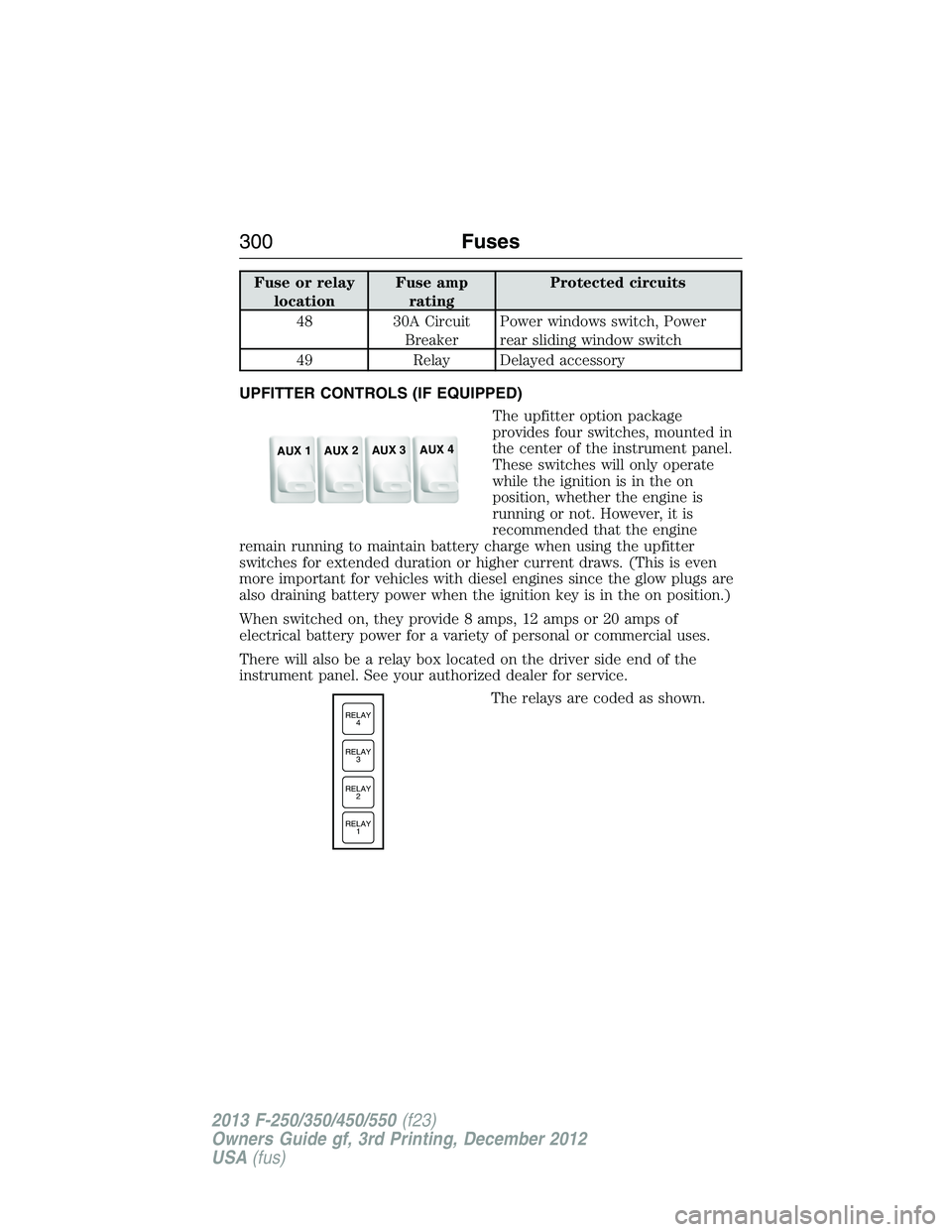
UPFITTER CONTROLS (IF EQUIPPED)
The upfitter option package
provides four switches, mounted in
the center of the instrument panel.
These switches will only operate
while the ignition is in the on
position, whether the engine is
running or not. However, it is
recommended that the engine
remain running to maintain battery charge when using the upfitter
switches for extended duration or higher current draws. (This is even
more important for vehicles with diesel engines since the glow plugs are
also draining battery power when the ignition key is in the on position.)
When switched on, they provide 8 amps, 12 amps or 20 amps of
electrical battery power for a variety of personal or commercial uses.
There will also be a relay box located on the driver side end of the
instrument panel. See your authorized dealer for service.
The relays are coded as shown.
AUX 1
AUX 2
AUX 3
AUX 4
RELAY
1 RELAY
2 RELAY
3 RELAY
4
300Fuses
2013 F-250/350/450/550(f23)
Owners Guide gf, 3rd Printing, December 2012
USA(fus)
Page 302 of 577
There will also be one power lead
for each switch found as a blunt-cut
and sealed wire located below the
instrument panel and to the left of
the steering column.
They are coded as follows:
SwitchCircuit
NumberWire ColorFuse Amp
Rating
AUX 1 CAC05 Yellow 25A
AUX 2 CAC06 Green with
Brown Trace25A
AUX 3 CAC07 Violet with
Green Trace10A
AUX 4 CAC08 Brown 15A
More detailed information about upfitter switches can be found at
https://www.fleet.ford.com/truckbbas/.
Fuses301
2013 F-250/350/450/550(f23)
Owners Guide gf, 3rd Printing, December 2012
USA(fus)
Page 304 of 577
Working with the Engine Off
1. Set the parking brake and shift toP(Park).
2. Turn off the engine and remove the key (if equipped).
3. Block the wheels.
Working with the Engine On
WARNING:To reduce the risk of vehicle damage or personal
burn injuries, do not start your engine with the air cleaner
removed and do not remove it while the engine is running.
1. Set the parking brake and shift to positionP.
2. Block the wheels.
OPENING AND CLOSING THE HOOD
1. Inside the vehicle, pull the hood
release handle located under the
bottom left corner of the instrument
panel.
2. Go to the front of the vehicle to
release the auxiliary latch located
at the top center of the grille.
Slide the handle left to release
the auxiliary latch.
3. Lift the hood until the lift
cylinders hold it open.
BRAKE
HOOD
Maintenance303
2013 F-250/350/450/550(f23)
Owners Guide gf, 3rd Printing, December 2012
USA(fus)