Page 296 of 577
Fuse or relay
locationFuse amp
ratingProtected circuits
88 20A* Auxiliary power point #6
89 40A* Starter motor
90 25A* Trailer tow battery charge
91 — Not used
92 20A* Auxiliary power point #4
93 20A* Auxiliary power point #3
94 25A* Upfitter #1
95 25A* Upfitter #2
96 50A* Anti-lock brake system pump
97 40A* Inverter
98 — Not used
99 40A* Instrument panel power inverter
100 25A* Trailer tow turn signals
101 Relay Starter
102 Relay Trailer tow battery charge
103 — Not used
104 — Not used
105 — Not used
106 — Not used
107 — Not used
* Cartridge fuses ** Mini fuses
Fuses295
2013 F-250/350/450/550(f23)
Owners Guide gf, 3rd Printing, December 2012
USA(fus)
Page 297 of 577
Passenger Compartment Fuse Panel
The fuse panel is located in the
passenger’s footwell. Remove the
panel cover to access the fuses.
To remove the fuse panel cover, pull
the panel toward you. When the
clips of the panel disengage, let the
panel fall easily.
To remove a fuse, use the fuse puller tool provided on the fuse panel
cover.
296Fuses
2013 F-250/350/450/550(f23)
Owners Guide gf, 3rd Printing, December 2012
USA(fus)
Page 299 of 577
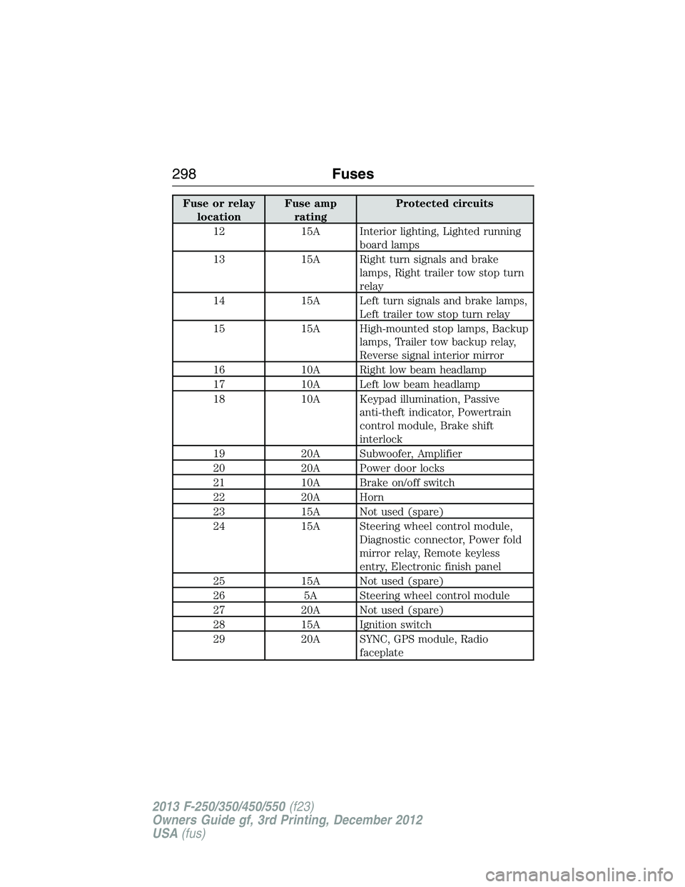
Fuse or relay
locationFuse amp
ratingProtected circuits
12 15A Interior lighting, Lighted running
board lamps
13 15A Right turn signals and brake
lamps, Right trailer tow stop turn
relay
14 15A Left turn signals and brake lamps,
Left trailer tow stop turn relay
15 15A High-mounted stop lamps, Backup
lamps, Trailer tow backup relay,
Reverse signal interior mirror
16 10A Right low beam headlamp
17 10A Left low beam headlamp
18 10A Keypad illumination, Passive
anti-theft indicator, Powertrain
control module, Brake shift
interlock
19 20A Subwoofer, Amplifier
20 20A Power door locks
21 10A Brake on/off switch
22 20A Horn
23 15A Not used (spare)
24 15A Steering wheel control module,
Diagnostic connector, Power fold
mirror relay, Remote keyless
entry, Electronic finish panel
25 15A Not used (spare)
26 5A Steering wheel control module
27 20A Not used (spare)
28 15A Ignition switch
29 20A SYNC, GPS module, Radio
faceplate
298Fuses
2013 F-250/350/450/550(f23)
Owners Guide gf, 3rd Printing, December 2012
USA(fus)
Page 300 of 577
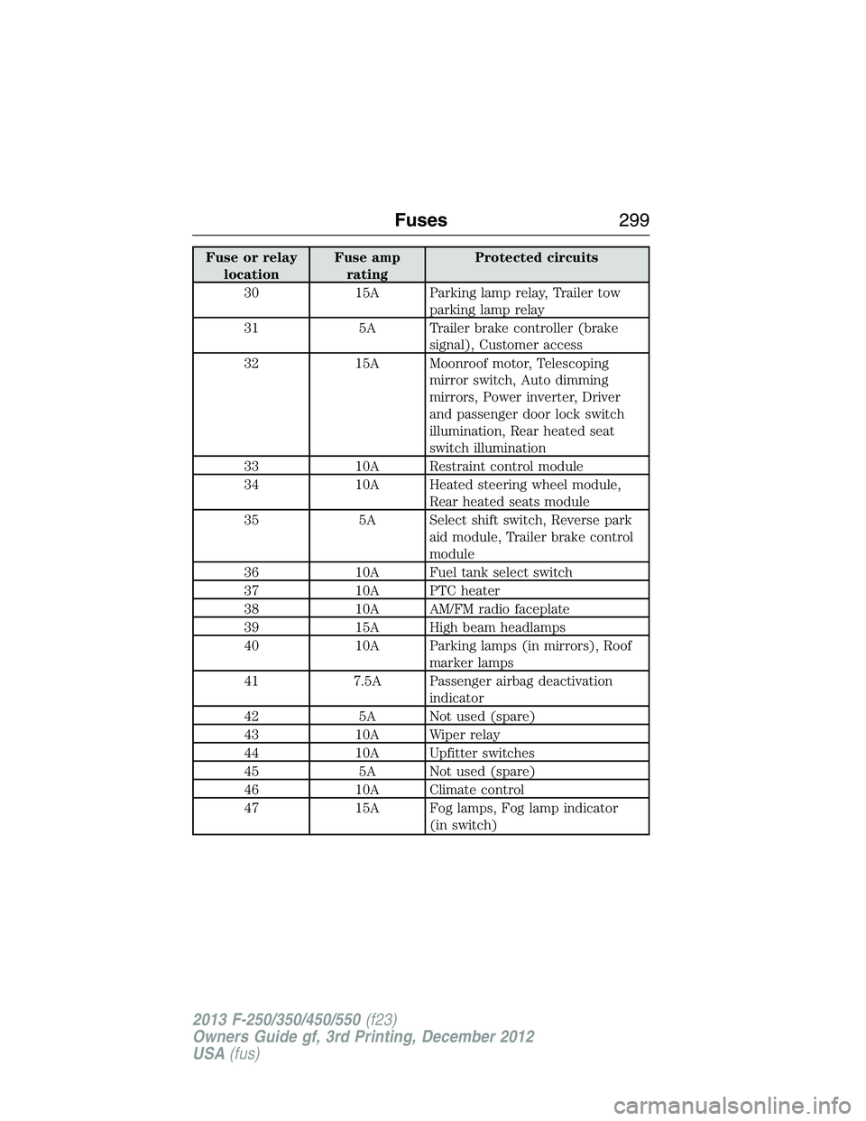
Fuse or relay
locationFuse amp
ratingProtected circuits
30 15A Parking lamp relay, Trailer tow
parking lamp relay
31 5A Trailer brake controller (brake
signal), Customer access
32 15A Moonroof motor, Telescoping
mirror switch, Auto dimming
mirrors, Power inverter, Driver
and passenger door lock switch
illumination, Rear heated seat
switch illumination
33 10A Restraint control module
34 10A Heated steering wheel module,
Rear heated seats module
35 5A Select shift switch, Reverse park
aid module, Trailer brake control
module
36 10A Fuel tank select switch
37 10A PTC heater
38 10A AM/FM radio faceplate
39 15A High beam headlamps
40 10A Parking lamps (in mirrors), Roof
marker lamps
41 7.5A Passenger airbag deactivation
indicator
42 5A Not used (spare)
43 10A Wiper relay
44 10A Upfitter switches
45 5A Not used (spare)
46 10A Climate control
47 15A Fog lamps, Fog lamp indicator
(in switch)
Fuses299
2013 F-250/350/450/550(f23)
Owners Guide gf, 3rd Printing, December 2012
USA(fus)
Page 312 of 577
When Fail-Safe Mode is Activated
WARNING:Never remove the coolant reservoir cap while the
engine is running or hot.
Note:Driving the vehicle without repairing the engine problem increases
the chance of engine damage. Take your vehicle to an authorized dealer
as soon as possible.
You have limited engine power when in the fail-safe mode, so drive the
vehicle with caution. The vehicle will not be able to maintain high-speed
operation and the engine will run rough. Remember that the engine is
capable of completely shutting down automatically to prevent engine
damage; therefore:
1. Pull off the road as soon as safely possible and turn off the engine.
2. Arrange for the vehicle to be taken to an authorized dealer.
3. If this is not possible, wait a short period for the engine to cool.
4. Check the coolant level and replenish if low.
5. Restart the engine and take your vehicle to an authorized dealer.
Engine Fluid Temperature Management (If Equipped)
WARNING:To reduce the risk of collision and injury, be
prepared that the vehicle speed may reduce and the vehicle may
not be able to accelerate with full power until the fluid temperatures
reduce.
Your vehicle has been designed to pull a trailer, but because of the added
load, the vehicle’s engine may temporarily reach higher temperatures
during severe operating conditions such as ascending a long or steep
grade while pulling a trailer in hot ambient temperatures.
At this time, you may notice your engine coolant temperature gauge
needle move toward the H and the POWER REDUCED TO LOWER
TEMP message may appear in the information display.
Maintenance311
2013 F-250/350/450/550(f23)
Owners Guide gf, 3rd Printing, December 2012
USA(fus)
Page 313 of 577
You may notice a reduction in the vehicle’s speed caused by reduced
engine power. Your vehicle has been designed to enter this mode if
certain high temperature/high load conditions take place in order to
manage the engine’s fluid temperatures. The amount of speed reduction
will depend on the vehicle loading, towing, grade, ambient temperature,
and other factors. If this occurs, there is no need to pull off the road.
The vehicle can continue to be driven while this message is active.
The air conditioning may also cycle on and off during severe operating
conditions to protect overheating of the engine. When the engine coolant
temperature decreases to a more normal operating temperature, the air
conditioning will turn on once again.
If you notice any of the following:
•the engine coolant temperature gauge moves fully into the red (hot)
area
•the coolant temperature warning light illuminates
•the service engine soon indicator illuminates
1. Pull off the road as soon as safely possible and place the vehicle inP
(Park).
2. Leave the engine running until the coolant temperature gauge needle
moves away from the H range. After several minutes, if this does not
happen, follow the remaining steps.
3. Turn the engine off and wait for it to cool before checking the coolant
level.
WARNING:Never remove the coolant reservoir cap while the
engine is running or hot.
4. If the coolant level is normal, you may restart your engine and
continue on.
5. If the coolant is low, add coolant, restart the engine and take your
vehicle to an authorized dealer. SeeAdding engine coolantin this
chapter for more information.
Refer to fail-safe cooling for additional information.
312Maintenance
2013 F-250/350/450/550(f23)
Owners Guide gf, 3rd Printing, December 2012
USA(fus)
Page 323 of 577
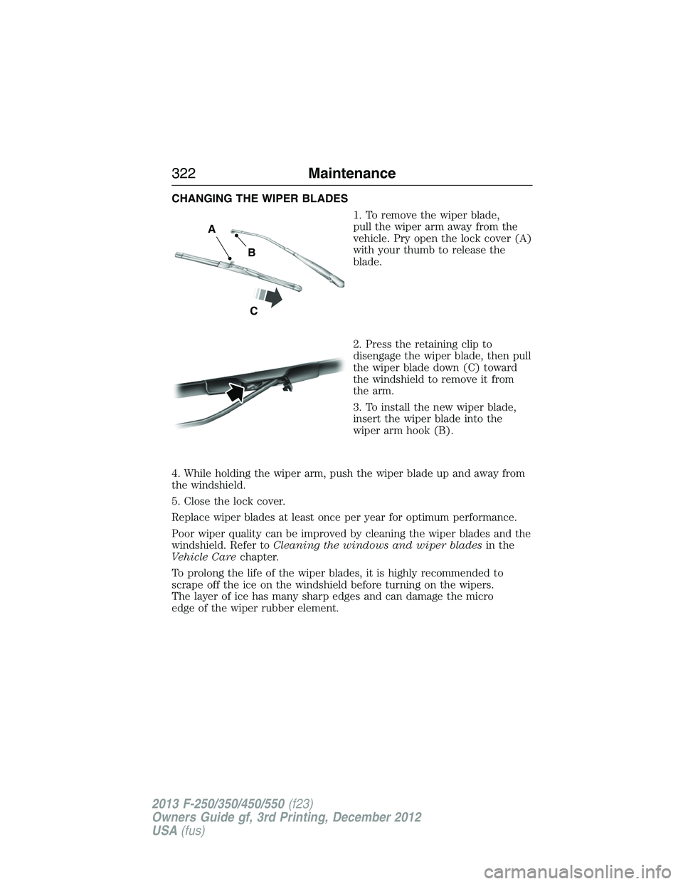
CHANGING THE WIPER BLADES
1. To remove the wiper blade,
pull the wiper arm away from the
vehicle. Pry open the lock cover (A)
with your thumb to release the
blade.
2. Press the retaining clip to
disengage the wiper blade, then pull
the wiper blade down (C) toward
the windshield to remove it from
the arm.
3. To install the new wiper blade,
insert the wiper blade into the
wiper arm hook (B).
4. While holding the wiper arm, push the wiper blade up and away from
the windshield.
5. Close the lock cover.
Replace wiper blades at least once per year for optimum performance.
Poor wiper quality can be improved by cleaning the wiper blades and the
windshield. Refer toCleaning the windows and wiper bladesin the
Vehicle Carechapter.
To prolong the life of the wiper blades, it is highly recommended to
scrape off the ice on the windshield before turning on the wipers.
The layer of ice has many sharp edges and can damage the micro
edge of the wiper rubber element.
A
B
C
322Maintenance
2013 F-250/350/450/550(f23)
Owners Guide gf, 3rd Printing, December 2012
USA(fus)
Page 325 of 577
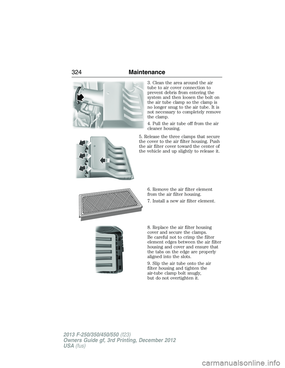
3. Clean the area around the air
tube to air cover connection to
prevent debris from entering the
system and then loosen the bolt on
the air tube clamp so the clamp is
no longer snug to the air tube. It is
not necessary to completely remove
the clamp.
4. Pull the air tube off from the air
cleaner housing.
5. Release the three clamps that secure
the cover to the air filter housing. Push
the air filter cover toward the center of
the vehicle and up slightly to release it.
6. Remove the air filter element
from the air filter housing.
7. Install a new air filter element.
8. Replace the air filter housing
cover and secure the clamps.
Be careful not to crimp the filter
element edges between the air filter
housing and cover and ensure that
the tabs on the edge are properly
aligned into the slots.
9. Slip the air tube onto the air
filter housing and tighten the
air-tube clamp bolt snugly,
but do not overtighten it.
324Maintenance
2013 F-250/350/450/550(f23)
Owners Guide gf, 3rd Printing, December 2012
USA(fus)