Page 6 of 39

•Dual exhaust, 3.5 inch exhaust tips
•Modified rear bumper with integrated rear tow hooks
•Heavy duty front skid plate and engine skid plate, and front tow hooks
•Cast aluminum running board/sill protector with Durabed�protection
•Front fenders with functional air extractors
•Seats with increased bolstering and unique covers
•Front and rear LED marker lamps
•Switch pack with off-road mode and hill descent buttons, and four
auxiliary switches
•Longer, cast aluminum lower control arms
•Longer, forged steel upper control arms
•Front coil springs and rear leaf springs
•Fox Racing 1.8 inch piston internal bypass front shocks
•Fox Racing 1.8 inch, internal bypass, remote reservoir rear shocks
•Micro-cellular urethane jounce bumpers (front and rear)
•Raptor navigation welcome screen
•Full-size all-terrain spare tire
•Off-road specific calibrations for engine, transmission and
AdvanceTrac�system
•Standard 17 inch Cast Aluminum Wheels
•Optional 17 inch forged aluminum beadlock compatible wheels
•LT 315/70-17 BF Goodrich�all-terrain tires
F-150 SVT Raptor-specific features
5
2013 F-150(f12)
Supplement, 1st Printing
USA(fus)
Page 8 of 39
6.2L V8 ENGINE
A. Auxiliary switch pass through circuits
B. Windshield washer fluid reservoir
C. Engine oil dipstick
D. Brake fluid reservoir
E. Engine coolant reservoir
F. Auxiliary power distribution box
G. Air filter assembly
H. Power steering fluid reservoir
I. Power distribution box
J. Engine oil filler cap
K. Battery
CDEF
GHIJK
AB
Engine/Transmission
7
2013 F-150(f12)
Supplement, 1st Printing
USA(fus)
Page 16 of 39

Whether accelerating or decelerating, once the desired descent speed is
reached, remove your feet from the pedals and the chosen vehicle speed
will be maintained.
See theInformation Displayschapter of yourOwner’s Manualfor hill
descent mode messages.
Disabling hill decent control
To disable hill decent control press the button located on the center
console a second time. A light on the button will turn off and a message
will appear indicating this feature has been disabled.
UPFITTER CONTROLS
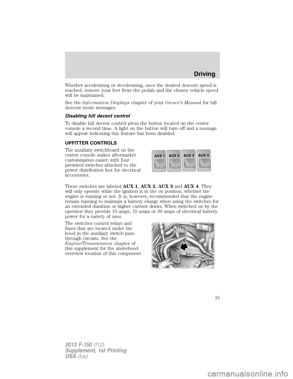
The auxiliary switchboard on the
center console makes aftermarket
customization easier, with four
prewired switches attached to the
power distribution box for electrical
accessories.
These switches are labeledAUX 1,AUX 2,AUX 3andAUX 4. They
will only operate while the ignition is in the on position, whether the
engine is running or not. It is, however, recommended that the engine
remain running to maintain a battery charge when using the switches for
an extended duration or higher current draws. When switched on by the
operator they provide 10 amps, 15 amps or 30 amps of electrical battery
power for a variety of uses.
The switches control relays and
fuses that are located under the
hood in the auxiliary switch pass
through circuits. See the
Engine/Transmissionchapter of
this supplement for the underhood
overview location of this component.
AUX 1
AUX 2
AUX 3
AUX 4
Driving
15
2013 F-150(f12)
Supplement, 1st Printing
USA(fus)
Page 17 of 39
There will also be one power lead
for each switch found as a blunt-cut
and sealed wire located to the right
of the glove box door and just above
the passenger side kick panel.
You may need to pull down the
auxiliary cords to access them.
Refer to theFuseschapter of your Owner’s Manual for information on
fuse and relay locations. See your authorized dealer for service.
Additional pass through circuits that run through the dash panel and
under the hood, are located in the same location.
The relays are coded as follows:
Switch Circuit number Wire color Fuse
AUX 1 CAC05 Yellow 30A
AUX 2 CAC06 Green with
Brown Trace30A
AUX 3 CAC07 Violet with
Green Trace15A
AUX 4 CAC08 Brown 10 A
i
Driving
16
2013 F-150(f12)
Supplement, 1st Printing
USA(fus)
Page 33 of 39

Item CapacityFord part name or
equivalentFord part number /
Ford Specification
Rear axle fluid friction
modifier4 oz. (118 ml) Additive Friction ModifierXL-3
EST-M2C118-A
SuperCab fuel tank 26 gallons (98.4L) — —
CrewCab fuel tank 36 gallons (136.3L) — —
Transmission fluid
3
12.4L
(13.1 quarts)
4
Motorcraft
MERCON�LV AT FXT-10-QLV /
MERCON�LV
Transfer case lubricant1.4-1.5L
(2.9-3.1 pints)Motorcraft Transfer Case
FluidXL-12 / —
1Add the coolant type originally equipped in your vehicle.2Fill 6 millimeter to 14 millimeter (1/4 inch to 9/16 inch) below bottom of fill hole.
Your vehicle’s rear axle is filled with a synthetic rear axle lubricant and is considered lubricated for
life. These lubricants do not need to be checked or changed unless a leak is suspected, service is
required or the axle assembly has been submerged in water. The axle lubricant should be changed
any time the rear axle has been submerged in water.3Ensure the correct automatic transmission fluid is used. Transmission fluid requirements are
indicated on the dipstick or on the dipstick handle. Check the container to verify the fluid being
added is of the correct type. Refer to yourscheduled maintenance informationto determine the
correct service interval.4Approximate dry fill capacity including transmission fluid cooling system, actual refill capacities
will vary based on vehicle application and transmission fluid cooling system (i.e. coolers size,
cooling lines, auxiliary cooler capacities). The amount of transmission fluid and fluid level should
be set by the indication on the dipstick’s normal operating range.5Use of synthetic or synthetic blend motor oil is not mandatory. Engine oil need only meet the
requirements of Ford specification WSS-M2C945-A and the API Certification mark.
Maintenance
32
2013 F-150(f12)
Supplement, 1st Printing
USA(fus)