Page 232 of 350
TIRE SAFETY INFORMATION
Tire MarkingsNOTE:
•P (Passenger) - Metric tire sizing is based on U.S.
design standards. P-Metric tires have the letter “P”
molded into the sidewall preceding the size designa-
tion. Example: P215/65R15 95H.
• European-Metric tire sizing is based on European
design standards. Tires designed to this standard have
the tire size molded into the sidewall beginning with
the section width. The letter �P�is absent from this tire
size designation. Example: 215/65R15 96H.
• LT (Light Truck) - Metric tire sizing is based on U.S.
design standards. The size designation for LT-Metric
tires is the same as for P-Metric tires except for the
letters “LT” that are molded into the sidewall preced-
ing the size designation. Example: LT235/85R16.
1 — U.S. DOT Safety Standards
Code (TIN) 4 — Maximum Load
2 — Size Designation 5 — Maximum Pressure
3 — Service Description 6 — Treadwear, Traction and Temperature Grades
230 STARTING AND OPERATING
Page 234 of 350
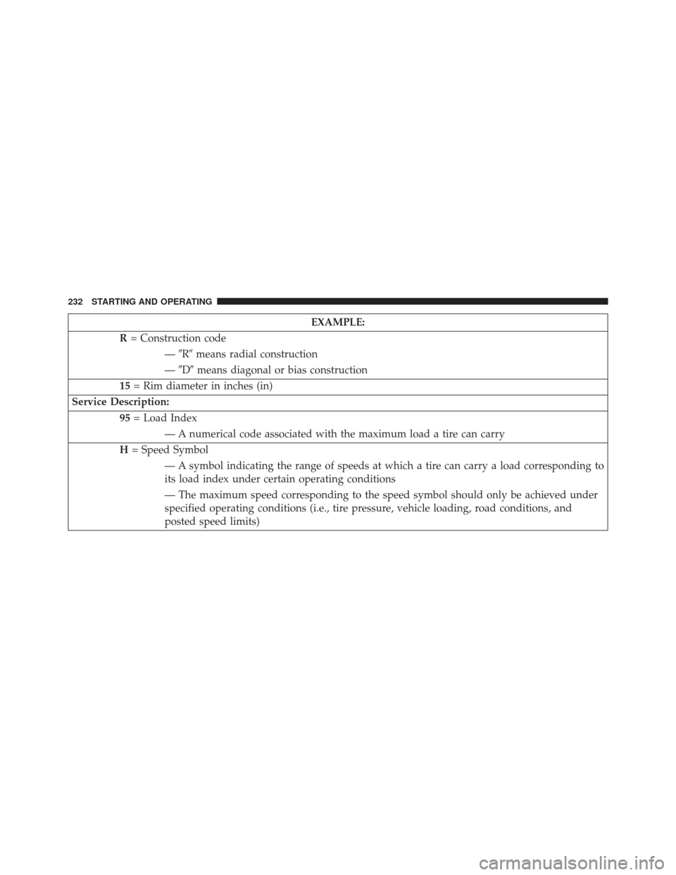
EXAMPLE:
R = Construction code
—�R� means radial construction
— �D� means diagonal or bias construction
15 = Rim diameter in inches (in)
Service Description: 95= Load Index
— A numerical code associated with the maximum load a tire can carry
H = Speed Symbol
— A symbol indicating the range of speeds at which a tire can carry a load corresponding to
its load index under certain operating conditions
— The maximum speed corresponding to the speed symbol should only be achieved under
specified operating conditions (i.e., tire pressure, vehicle loading, road conditions, and
posted speed limits)
232 STARTING AND OPERATING
Page 246 of 350

Consult an authorized tire dealer for tire repairs and
additional information.
Damaged Run Flat tires, or Run Flat tires that have
experienced a loss of pressure should be replaced imme-
diately with another Run Flat tire of identical size and
service description (Load Index and Speed Code).
All Season Tires – If Equipped
All Season tires provide traction for all seasons (spring,
summer, fall and winter). Traction levels may vary be-
tween different all season tires. All season tires can be
identified by the M+S, M&S, M/S or MS designation on
the tire sidewall. Use all season tires only in sets of four;
failure to do so may adversely affect the safety and
handling of your vehicle.
Summer Or Three Season Tires – If Equipped
Summer tires provide traction in both wet and dry
conditions, and are not intended to be driven in snow or
on ice. Summer tires will not contain the all season
designation or mountain/snowflake symbol on the tire
sidewall. Use summer tires only in sets of four; failure to
do so may adversely affect the safety and handling of
your vehicle.
Snow Tires
Some areas of the country require the use of snow tires
during the winter. Snow tires can be identified by a
mountain/snowflake symbol on the tire sidewall.
If you need snow tires, select tires equivalent in size and
type to the original equipment tires. Use snow tires only
in sets of four; failure to do so may adversely affect the
safety and handling of your vehicle.
244 STARTING AND OPERATING
Page 248 of 350
Tread Wear Indicators
Tread wear indicators are in the original equipment tires
to help you in determining when your tires should be
replaced.These indicators are molded into the bottom of the tread
grooves. They will appear as bands when the tread depth
becomes 1/16 in (2 mm). When the tread is worn to the
tread wear indicators, the tire should be replaced. Refer
to “Replacement Tires” in this section for further infor-
mation.
Life Of Tire
The service life of a tire is dependent upon varying
factors including, but not limited to:
•
Driving style
• Tire pressure
• Distance driven
• Performance tires, tires with a speed rating of V or
higher, and summer tires typically have a reduced
tread life. Rotation of these tires per the vehicle main-
tenance schedule is highly recommended.
1—WornTire
2—NewTire 246 STARTING AND OPERATING
Page 258 of 350
TPMS Warning
When a system fault is detected, the “Tire Pressure
Monitoring Telltale Light” will flash on and off for 75
seconds and then remain on solid. The system fault will
also sound a chime. In addition, the EVIC will display a
“Service TPM System” message for a minimum of five
seconds and then display dashes (- -) in place of the
pressure value to indicate which sensor is not being
receivedIf the ignition switch is cycled, this sequence will repeat,
providing the system fault still exists. If the system fault
no longer exists, the “Tire Pressure Monitoring Telltale
Light” will no longer flash, and the “Service TPM Sys-
tem” message will no longer display, and a pressure
value will display in place of the dashes.
Service TPM System Message
256 STARTING AND OPERATING
Page 259 of 350

NOTE:
•The TPMS will not monitor the pressure in a replace-
ment tire installed without a tire pressure sensor.
• If you install a replacement tire in place of a road tire
that has a pressure below the low-pressure warning
limit, upon the next ignition switch cycle, the “Tire
Pressure Monitoring Telltale Light” will remain on and
a chime will sound. In addition, the graphic in the
EVIC will still display a pressure value in a different
color.
• After driving the vehicle for up to 20 minutes above
15 mph (24 km/h), the “Tire Pressure Monitoring
Telltale Light” will flash on and off for 75 seconds and
then remain on solid. In addition, the EVIC will
display a “Service TPM System” message for a mini-
mum of five seconds and then display dashes (- -) in
place of the pressure value. •
For each subsequent ignition switch cycle, a chime will
sound, the “Tire Pressure Monitoring Telltale Light”
will flash on and off for 75 seconds and then remain on
solid, and the EVIC will display a “Service TPM
System” message for a minimum of five seconds and
then display dashes (- -) in place of the pressure value.
Once you repair or replace the original road tire and
reinstall it, the TPMS will update automatically. In addi-
tion, the “Tire Pressure Monitoring Telltale Light” will
turn off and the graphic in the EVIC will display a new
pressure value instead of dashes (- -), as long as no tire
pressure is below the low-pressure warning limit in any
of the four active road tires. The vehicle may need to be
driven for up to 20 minutes above 15 mph (24 km/h) in
order for the TPMS to receive this information.
5
STARTING AND OPERATING 257
Page 266 of 350

HAZARD WARNING FLASHERS
The Hazard Warning flasher switch is located on the
instrument panel below the radio.Press the switch to turn on the Hazard Warning
flashers. When the switch is activated, all direc-
tional turn signals will flash on and off to warn oncoming
traffic of an emergency. Press the switch a second time to
turn off the Hazard Warning flashers.
Do not use this emergency warning system when the
vehicle is in motion. Use it when your vehicle is disabled
and it is creating a safety hazard for other motorists.
If it is necessary to leave the vehicle to go for service, the
Hazard Warning flashers will continue to operate with
the ignition key removed and the vehicle locked. NOTE:
With extended use, the Hazard Warning flashers
may wear down your battery.
TIREFIT KIT
Small punctures up to ¼” (6 mm) in the tire tread can be
sealed with TIREFIT. Foreign objects (e.g., screws or
nails) should not be removed from the tire. TIREFIT can
be used in outside temperatures down to approximately
-4°F (-20°C).
This kit will provide a temporary tire seal, allowing you
to drive your vehicle up to 100 miles (160 km) with a
maximum speed of 55 mph (88 km/hr).
264 WHAT TO DO IN EMERGENCIES
Page 275 of 350

2. Disconnect the TIREFIT kit from the valve stem,reinstall the cap on the valve stem and unplug from 12
Volt outlet.
3. Place the TIREFIT kit in its proper storage area in the vehicle.
4. Have the tire inspected and repaired or replaced at the earliest opportunity at an authorized studio or tire
service center.
5. Replace the Sealant Bottle (1) and Sealant Hose (6) assembly at your authorized studio as soon as pos-
sible. Refer to “(F) Sealant Bottle and Hose Replace-
ment.”
NOTE: When having the tire serviced, advise the autho-
rized studio or service center that the tire has been sealed
using the TIREFIT service kit.(F) Sealant Bottle And Hose Replacement:
1. Uncoil the Sealant Hose (6) (clear in color).
2. Locate the round Sealant Bottle release button in the recessed area under the sealant bottle.
3. Press the Sealant Bottle release button. The Sealant Bottle (1) will pop up. Remove the bottle and dispose
of it accordingly.
4. Clean any remaining sealant from the TIREFIT hous- ing.
5. Position the new Sealant Bottle (1) in the housing so that the Sealant Hose (6) aligns with the hose slot in
the front of the housing. Press the bottle into the
housing. An audible click will be heard indicating the
bottle is locked into place.
6
WHAT TO DO IN EMERGENCIES 273
 - Metric tire sizing is based on U.S.
design standards. P-Metric tires have the letter “P”
molded into the sidewall preceding the size d")