Page 311 of 350
CavityVehicle
Fuse
Number Mini
Fuse Description
5 F36 10 Amp RedDiagnostic Socket,
Car Radio, Climate
Control System,
Tire Pressure Moni-
tor, TCU and CTM
6 F43 20 Amp YellowBi-Directional
Washer
7 F48 20 Amp YellowPassenger Power
Window
8 F13 7.5 Amp
Brown Left Low Beam
9 F50 7.5 Amp
Brown AirbagCavity
Vehicle
Fuse
Number Mini
Fuse Description
10 F51 5 Amp Ta nCar Radio Switch,
Climate Control
System, Stop Light,
Exterior Mirrors,
Sunroof Switch,
GPS (option) and
CTM
11 F37 5 Amp Ta nStop Light Switch,
Instrument Panel
Node
12 F49 5 Amp Ta nExterior Mirror,
GPS, Electric Mir-
ror, Parking Sensor,
Sunroof Switch
7
MAINTAINING YOUR VEHICLE 309
Page 312 of 350
CavityVehicle
Fuse
Number Mini
Fuse Description
13 F31 5 Amp Ta nIgnition, Climate
Control, RDU and
EVCU
14 F47 20 Amp YellowDriver Power Win-
dow
Power Distribution Center #1
The Power Distribution Center #1 is located on the right
side of the underhood compartment. To access the fuses,
remove locking screw and slide cover off.
The ID number of the electrical component correspond-
ing to each fuse can be found on the back of the cover.
Front Distribution Unit
310 MAINTAINING YOUR VEHICLE
Page 313 of 350
CavityMaxi
Fuse Mini Fuse Description
F01 60 Amp Blue Body Control
Module (BCM)
F02 20 Amp Yellow HiFi Amplifier
F03 20 Amp Yellow Ignition Switch
F04 40 Amp Orange Brake System
Module Pump
F05 70 Amp Ta n Electric Power
Steering (EPS)
F06 60 Amp Blue Radiator Fan
F07 40 Amp Orange Regen Brake Mod-
uleCavity
Maxi
Fuse Mini Fuse Description
F08 40 Amp Orange HVAC
F09 5 Amp
Ta n Air Electric Heater
Charge Indicator
F10 10 Amp
Red Horn
F11 10 Amp
Red Electronic Vehicle
Control Unit
(EVCU)
F14 5 Amp
Ta n High beam (Shut-
ter)
F15 15 Amp
Blue Cigar Lighter
7
MAINTAINING YOUR VEHICLE 311
Page 314 of 350
CavityMaxi
Fuse Mini Fuse Description
F16 10 Amp
Red Humidity Sensor
VPAM
AC Compressor
F18 5 Amp
Ta n Electronic Vehicle
Control Unit
(EVCU)
F19 10 Amp
Red HVAC
F20 15 Amp
Blue Heated Seats – If
Equipped
F23 25 Amp
Clear Anti-Lock Brake
Valves
F24 7.5 Amp
Brown EPS
YAW SensorCavity
Maxi
Fuse Mini Fuse Description
F30 15 Amp
Blue Fog Lamps
F81 30 Amp Green Electronic Shifter
(ESM)
F82 30 Amp Green Sunroof
F84 25 Amp
Clear Regen Brake Mod-
ule
F85 30 Amp Green Rear Window
Heater
F87 5 Amp
Ta n Electronic Shifter
(ESM)
312 MAINTAINING YOUR VEHICLE
Page 315 of 350
Power Distribution Center (PDC) #2
The Power Distribution Center #2 is located next to the
battery in the underhood compartment. To access the
fuses, pull the release tabs and remove the cover.
Cavity MaxiFuseMini
Fuse Description
FPT9 15 Amp
BlueBattery Pack Con-
trol Module
(BPCM)
Power Inverter
Module (PIM)
FPT13 10 Amp
Red EAC (AC Com-
pressor)
On Board Charg-
ing Module
(OBCM)
FPT16 5 Amp
Ta n Intelligent Battery
Sensor (IBS)
FPT17 10 Amp
Red EAC (AC Com-
pressor)
Radiator Fan
PDC #2
7
MAINTAINING YOUR VEHICLE 313
Page 316 of 350
FPT2010 Amp
Red Electronic Vehicle
Control Unit
(EVCU)
Cavity
Cartridge Fuse Description
FPT3 25 Amp Clear Batt Coolant
Pump
FPT5 20 Amp Yellow Inverter Coolant
Pump
VEHICLE STORAGE
The preferred way of storing your vehicle for a long
period of time is to leave it attached to a Level 1 or Level
2 charger. The vehicle has a wake-up feature that will
wake the system every 3 weeks and do a maintenance
charge on the 12 Volt battery and also top off the high
voltage battery if necessary. Anytime you store your vehicle, or keep it out of service
(i.e., vacation) for two weeks or more, run the air
conditioning system at idle for about five minutes in the
fresh air and high blower setting. This will ensure
adequate system lubrication to minimize the possibility
of compressor damage when the air conditioning system
is started again.
REPLACEMENT BULBS
Interior Bulbs
Bulb Number
Overhead Lamp C5W
Courtesy Lamp W5W
314 MAINTAINING YOUR VEHICLE
Page 342 of 350

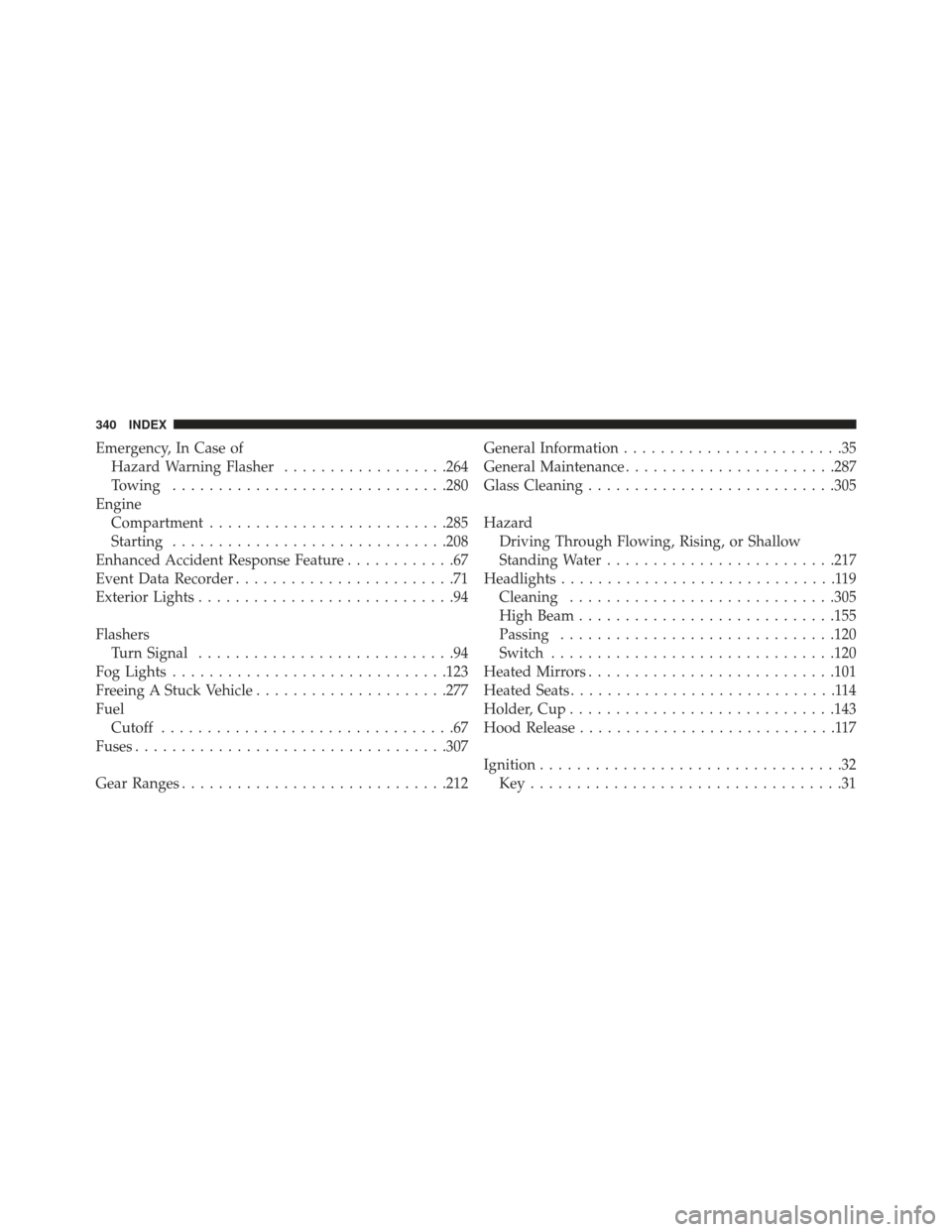
Emergency, In Case ofHazard Warning Flasher ..................264
Towing ............................. .280
Engine Compartment ......................... .285
Starting ............................. .208
Enhanced Accident Response Feature ............67
Event Data Recorder ........................71
Exterior Lights ............................94
Flashers Turn Signal ............................94
Fog Lights ............................. .123
Freeing A Stuck Vehicle .....................277
Fuel Cutoff ................................67
Fuses ................................. .307
Gear Ranges ............................ .212General Information
........................35
General Maintenance ...................... .287
Glass Cleaning .......................... .305
Hazard Driving Through Flowing, Rising, or Shallow
Standing Water ........................ .217
Headlights ..............................119
Cleaning ............................ .305
High Beam ........................... .155
Passing ............................. .120
Switch .............................. .120
Heated Mirrors .......................... .101
Heated Seats .............................114
Holder, Cup ............................ .143
Hood Release ............................117
Ignition .................................32
Key..................................31
340 INDEX
Page 349 of 350

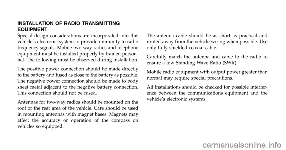
INSTALLATION OF RADIO TRANSMITTING
EQUIPMENT
Special design considerations are incorporated into this
vehicle’s electronic system to provide immunity to radio
frequency signals. Mobile two-way radios and telephone
equipment must be installed properly by trained person-
nel. The following must be observed during installation.
The positive power connection should be made directly
to the battery and fused as close to the battery as possible.
The negative power connection should be made to body
sheet metal adjacent to the negative battery connection.
This connection should not be fused.
Antennas for two-way radios should be mounted on the
roof or the rear area of the vehicle. Care should be used
in mounting antennas with magnet bases. Magnets may
affect the accuracy or operation of the compass on
vehicles so equipped.The antenna cable should be as short as practical and
routed away from the vehicle wiring when possible. Use
only fully shielded coaxial cable.
Carefully match the antenna and cable to the radio to
ensure a low Standing Wave Ratio (SWR).
Mobile radio equipment with output power greater than
normal may require special precautions.
All installations should be checked for possible interfer-
ence between the communications equipment and the
vehicle’s electronic systems.