Page 153 of 388

CAUTION!
The TPMS has been optimized for the original
equipment tires and wheels. TPMS pressures and
warning have been established for the tire size
equipped on your vehicle. Undesirable system opera-
tion or sensor damage may result when using re-
placement equipment that is not of the same size,
type, and/or style. Aftermarket wheels can cause
sensor damage. Do not use tire sealant from a can or
balance beads if your vehicle is equipped with a
TPMS, as damage to the sensors may result.
16. Automatic Gearbox Failure
This light will illuminate when there is an
automatic transmission fault.
17. Oil Pressure Warning Light
This light indicates low engine oil pressure. The
light should turn on momentarily when the engine is
started. If the light turns on while driving, stop the
vehicle and shut off the engine as soon as possible. A
chime will sound when this light turns on.
Do not operate the vehicle until the cause is corrected.
This light does not indicate how much oil is in the engine.
The engine oil level must be checked under the hood.
18. Malfunction Indicator Light (MIL)
The Malfunction Indicator Light (MIL) is part of
an onboard diagnostic system, called OBDII, that
monitors engine and automatic transmission con-
trol systems. The light will illuminate when the key is in
the ON/RUN position before engine start. If the bulb
does not come on when turning the key from OFF/LOCK
to ON/RUN, have the condition checked promptly.
4
UNDERSTANDING YOUR INSTRUMENT PANEL 151
Page 205 of 388
STEERING WHEEL AUDIO CONTROLS
The remote sound system controls are located on the rear
surface of the steering wheel. Reach behind the wheel to
access the switches.
The right-hand control is a rocker-type switch with a
pushbutton in the center and controls the volume and
mode of the sound system. Pressing the top of the rocker
switch will increase the volume, and pressing the bottom
of the rocker switch will decrease the volume.
Pressing the center button will make the radio switch
between the various modes available (AM/FM/SAT/
CD/AUX/Media Player, etc.) and can also be used to
select/enter an item while scrolling through menu.
The left-hand control is a rocker-type switch with a
pushbutton in the center. The function of the left-hand
control is different depending on which mode you are in.
The following describes the left-hand control operation in
each mode.
Remote Sound System Controls (Back View Of Steering
Wheel)
4
UNDERSTANDING YOUR INSTRUMENT PANEL 203
Page 216 of 388

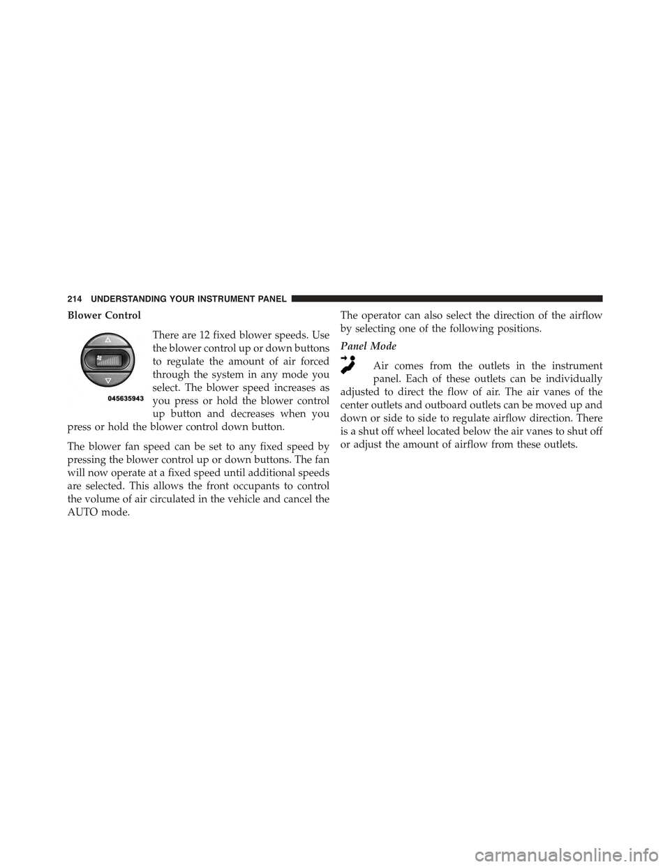
Blower Control
There are 12 fixed blower speeds. Use
the blower control up or down buttons
to regulate the amount of air forced
through the system in any mode you
select. The blower speed increases as
you press or hold the blower control
up button and decreases when you
press or hold the blower control down button.
The blower fan speed can be set to any fixed speed by
pressing the blower control up or down buttons. The fan
will now operate at a fixed speed until additional speeds
are selected. This allows the front occupants to control
the volume of air circulated in the vehicle and cancel the
AUTO mode.
The operator can also select the direction of the airflow
by selecting one of the following positions.
Panel Mode
Air comes from the outlets in the instrument
panel. Each of these outlets can be individually
adjusted to direct the flow of air. The air vanes of the
center outlets and outboard outlets can be moved up and
down or side to side to regulate airflow direction. There
is a shut off wheel located below the air vanes to shut off
or adjust the amount of airflow from these outlets.
214 UNDERSTANDING YOUR INSTRUMENT PANEL
Page 224 of 388

!SPORT MODE.........................236
!BRAKE SYSTEM.......................237
▫Four-Wheel Anti-Lock Brake System (ABS) . . .237
!ELECTRONIC BRAKE CONTROL SYSTEM . . . .238
▫Anti-Lock Brake System (ABS)............239
▫Brake Assist System (BAS)...............239
▫Traction Control System (TCS)............240
▫Hill Start Assist (HSA).................240
▫Electronic Stability Control (ESC)..........241
▫ESC Activation/Malfunction Indicator Light And
ESC OFF Indicator Light................244
!TIRE SAFETY INFORMATION.............245
▫Tire Markings........................245
▫Tire Identification Number (TIN)...........249
▫Tire Terminology And Definitions..........251
▫Tire Loading And Tire Pressure...........252
!TIRES — GENERAL INFORMATION........256
▫Tire Pressure........................256
▫Tire Inflation Pressures.................257
▫Tire Pressures For High Speed Operation . . . .258
▫Radial Ply Tires......................259
▫All Season Tires – If Equipped............260
▫Snow Tires..........................260
▫Summer Or Three Season Tires – If Equipped. .260
▫Spare Tire Matching Original Equipped Tire And
Wheel – If Equipped...................261
222 STARTING AND OPERATING
Page 231 of 388

Downshifting
Proper downshifting will improve fuel economy and
prolong engine life.
CAUTION!
If you skip a gear while downshifting or downshift
at too high of a vehicle speed, these conditions may
cause the engine to overspeed if too low of a gear is
selected and the clutch pedal is released. Damage to
the clutch and the transmission can result from
skipping a gear while downshifting or downshifting
at too high of a vehicle speed even if the clutch pedal
is held pressed (i.e., not released).
To maintain a safe speed and prolong brake life, shift
down to second or first gear when descending a steep
grade.
When turning a corner or driving up a steep grade,
downshift early so that the engine will not be overbur-
dened.
DRIVING ON SLIPPERY SURFACES
Acceleration
Rapid acceleration on snow covered, wet, or other slip-
pery surfaces may cause the driving wheels to pull
erratically to the right or left. This phenomenon occurs
when there is a difference in the surface traction under
the front (driving) wheels.
WARNING!
Rapid acceleration on slippery surfaces is dangerous.
Unequal traction can cause sudden pulling of the
front wheels. You could lose control of the vehicle
(Continued)
5
STARTING AND OPERATING 229
Page 236 of 388
PARKING BRAKE
Before leaving the vehicle, make sure that the parking
brake is fully applied. Also, be certain to leave manual
transmission in REVERSE or first gear.
The parking brake lever is located in the center console.
To apply the parking brake, pull the lever up as firmly as
possible. To release the parking brake, pull the lever up
slightly, press the center button, then lower the lever
completely.
When the parking brake is applied with the ignition
switch in the MAR (ACC/ON/RUN) position, the Brake
Warning Light in the instrument cluster will illuminate.
When parking on a hill, it is important to turn the front
wheels toward the curb on a downhill grade and away
from the curb on an uphill grade. The parking brake
Parking Brake
234 STARTING AND OPERATING
Page 239 of 388

BRAKE SYSTEM
In the event power assist is lost for any reason (for
example; repeated brake applications with the engine
off), the brakes will still function. The effort required to
brake the vehicle will be significantly more than that
required with the power system operating.
If either of the two hydraulic systems loses normal
capability, the remaining system will still function with
some loss of braking effectiveness. This will be evident by
increased pedal travel during application, greater pedal
force required to slow or stop, and activation of the Brake
Warning Light and the ABS Warning Light during brake
use.
Four-Wheel Anti-Lock Brake System (ABS)
The Four-Wheel ABS is designed to aid the driver in
maintaining vehicle control under adverse braking con-
ditions. The system operates with a separate computer to
modulate hydraulic pressure, to prevent wheel lock-up
and to help avoid skidding on slippery surfaces.
The system’s pump motor runs during an ABS stop to
provide regulated hydraulic pressure. The pump motor
makes a low humming noise during operation, which is
normal.
The ABS includes an amber ABS Warning Light. When
the light is illuminated, the ABS is not functioning. The
system reverts to standard non-anti-lock brakes. Turning
the ignition Off and On again may reset the ABS if the
fault detected was only momentary.
5
STARTING AND OPERATING 237
Page 241 of 388

Anti-Lock Brake System (ABS)
This system aids the driver in maintaining vehicle control
under adverse braking conditions. The system controls
hydraulic brake pressure to prevent wheel lockup and
help avoid skidding on slippery surfaces during braking.
Refer to “Four-Wheel Anti-Lock Brake System” in “Start-
ing and Operating” for further information.
Brake Assist System (BAS)
The BAS is designed to optimize the vehicle’s braking
capability during emergency braking maneuvers. The
system detects an emergency braking situation by sens-
ing the rate and amount of brake application and then
applies optimum pressure to the brakes. This can help
reduce braking distances. The BAS complements the
Anti-Lock Brake System (ABS). Applying the brakes very
quickly results in the best BAS assistance. To receive the
benefit of the system, you must applycontinuousbrak-
ing pressure during the stopping sequence (do not
“pump” the brakes). Do not reduce brake pedal pressure
unless braking is no longer desired. Once the brake pedal
is released, the BAS is deactivated.
WARNING!
•The Brake Assist System (BAS) cannot prevent the
natural laws of physics from acting on the vehicle,
nor can it increase the traction afforded by prevail-
ing road conditions.
•The BAS cannot prevent collisions, including those
resulting from excessive speed in turns, driving on
very slippery surfaces, or hydroplaning.
•The capabilities of a BAS-equipped vehicle must
never be exploited in a reckless or dangerous
manner which could jeopardize the user ’s safety or
the safety of others.
5
STARTING AND OPERATING 239