2013 DODGE GRAND CARAVAN warning lights
[x] Cancel search: warning lightsPage 36 of 683

Cancel Remote Start
Remote Starting will also cancel if any of the following
occur:
•The engine stalls or engine speed exceeds 2500 rpm
•Any engine warning lights come on
•Low Fuel Light turns on
•The hood is opened
•The hazard switch is pressed
•The shift lever is moved out of PARK
•The engine is allowed to run for the entire 15-minute
cycle
•The brake pedal is pressedTo Turn Off The Engine While In Remote Start Mode
Press and release the REMOTE START button 1 time or
allow the engine to run for the entire 15 minute cycle.
NOTE:To avoid unintentional shutdowns while in the
Remote Start Mode, the system will not allow the Remote
Start button to shut down the engine for 2 seconds after
receiving a valid Remote Start request.
When To Reset Remote Start
The vehicle can be started remotely up to a maximum of
two times. The vehicle is also allowed a maximum of one
failed start, where the Remote Starting sequence was
initiated but the engine stopped cranking without start-
ing. After either of these conditions, or if the Vehicle
Security Alarm system is alarming, or if the PANIC
button was pressed, the vehicle must be reset insert the
Key Fob into the ignition switch and turn the switch to
the ON/RUN position.
34 THINGS TO KNOW BEFORE STARTING YOUR VEHICLE
Page 56 of 683

The power liftgate may be closed by pressing the button,
located in the upper left trim in the liftgate opening.
Pushing once will only close the liftgate. This button
cannot be used to open the liftgate.
When the RKE transmitter button is pressed and the
Flash Lights feature is enabled, the tail lights will flashand several audible beeps will occur to signal that the
liftgate is opening or closing.
WARNING!
During power operation, personal injury or cargo
damage may occur. Ensure the liftgate travel path is
clear. Make sure the liftgate is closed and latched
before driving away.
NOTE:
•If anything obstructs the power liftgate while it is
closing or opening, the liftgate will automatically
reverse to the closed or open position, provided it
meets sufficient resistance.
•There are also pinch sensors attached to the side of the
liftgate opening. Light pressure anywhere along these
strips will cause the liftgate to return to the open
position.
Rear Power Liftgate Switch
54 THINGS TO KNOW BEFORE STARTING YOUR VEHICLE
Page 79 of 683

•Supplemental Side Air Bag Inflatable Curtains (SABIC)
•Front and Side Impact Sensors
•Front Seat Belt Pretensioners, Seat Belt Buckle Switch,
and Seat Track Position Sensors
Advanced Front Air Bag Features
The Advanced Front Air Bag system has multistage
driver and front passenger air bags. This system provides
output appropriate to the severity and type of collision as
determined by the Occupant Restraint Controller (ORC),
which may receive information from the front impact
sensors.
The first stage inflator is triggered immediately during an
impact that requires air bag deployment. This low output
is used in less severe collisions. A higher energy output is
used for more severe collisions.
WARNING!
•No objects should be placed over or near the air bag
on the instrument panel, because any such objects
could cause harm if the vehicle is in a collision
severe enough to cause the air bag to inflate.
•Do not put anything on or around the air bag
covers or attempt to open them manually. You may
damage the air bags and you could be injured
because the air bags may no longer be functional.
The protective covers for the air bag cushions are
designed to open only when the air bags are
inflating.
•Do not drill, cut or tamper with the knee bolster in
any way.
•
Do not mount any accessories to the knee bolster
such as alarm lights, stereos, citizen band radios, etc.
2
THINGS TO KNOW BEFORE STARTING YOUR VEHICLE 77
Page 122 of 683

WARNING!(Continued)
•Never put floor mats or other floor coverings on top
of already installed floor mats. Additional floor
mats and other coverings will reduce the size of the
pedal area and interfere with the pedals.
•Check mounting of mats on a regular basis. Always
properly reinstall and secure floor mats that have
been removed for cleaning.
•
Always make sure that objects cannot fall into the
driver footwell while the vehicle is moving. Objects
can become trapped under the brake pedal and accel-
erator pedal causing a loss of vehicle control.
•If required, mounting posts must be properly in-
stalled, if not equipped from the factory.
Failure to properly follow floor mat installation or
mounting can cause interference with the brake
pedal and accelerator pedal operation causing loss of
control of the vehicle.
Periodic Safety Checks You Should Make Outside
The Vehicle
Tires
Examine tires for excessive tread wear and uneven wear
patterns. Check for stones, nails, glass, or other objects
lodged in the tread or sidewall. Inspect the tread for cuts
and cracks. Inspect sidewalls for cuts, cracks and bulges.
Check the wheel nuts for tightness. Check the tires
(including spare) for proper cold inflation pressure.
Lights
Have someone observe the operation of brake lights and
exterior lights while you work the controls. Check turn
signal and high beam indicator lights on the instrument
panel.
120 THINGS TO KNOW BEFORE STARTING YOUR VEHICLE
Page 190 of 683

Heated Seats — If Equipped
On some models, the front and rear seats may be
equipped with heaters located in the seat cushions.
WARNING!
•Persons who are unable to feel pain to the skin
because of advanced age, chronic illness, diabetes,
spinal cord injury, medication, alcohol use, exhaus-
tion or other physical condition must exercise care
when using the seat heater. It may cause burns
even at low temperatures, especially if used for
long periods of time.
•Do not place anything on the seat or seatback that
insulates against heat, such as a blanket or cushion.
This may cause the seat heater to overheat. Sitting
in a seat that has been overheated could cause
serious burns due to the increased surface tempera-
ture of the seat.
Vehicles Equipped With Remote Start
On models that are equipped with remote start, the driv-
er ’s heated seat can be programmed to come on during a
remote start. Refer to “Remote Starting System — If
Equipped” in “Things To Know Before Starting Your
Vehicle” for further information.
Front Heated Seats
There are two heated seat switches that allow the driver
and passenger to operate the seats independently. The
controls for each heater are located on the switch bank
below the climate controls.
You can choose from HIGH, LOW or OFF heat settings.
Amber indicator lights in each switch indicate the level of
heat in use. Two indicator lights will illuminate for
HIGH, one for LOW and none for OFF.
188 UNDERSTANDING THE FEATURES OF YOUR VEHICLE
Page 230 of 683

Turn Signal Warning
If the vehicle electronics sense that the vehicle has
traveled at over 18 mph (29 km/h) for about 1 mile
(1.6 km) with the turn signals on, a chime will sound to
alert the driver.
Lane Change Assist
Tap the lever up or down once, without moving beyond
the detent, and the turn signal (right or left) will flash
three times then automatically turn off.
High/Low Beam Switch
When the headlights are turned on, pushing the multi-
function lever toward the instrument panel will switch
from low beams to high beams. Pulling back to the
neutral position returns the headlights to the low beam
operation.
Flash-To-Pass
You can signal another vehicle with your headlights by
lightly pulling the multifunction lever toward you. This
will cause the headlights to turn on at high beam and
remain on until the lever is released.
Battery Protection
This feature provides battery protection to avoid wearing
down the battery if the headlights, parking lights, or front
fog lights are left on for extended periods of time when the
ignition switch is in the LOCK position. After eight min-
utes of the ignition switch being in the LOCK position and
the headlight switch in any position other than OFF or
AUTO, the lights will turn off automatically until the next
cycle of the ignition switch or headlight switch.
The battery protection feature will be disabled if the
ignition switch is turned to any other position other than
LOCK during the eight minute delay.
228 UNDERSTANDING THE FEATURES OF YOUR VEHICLE
Page 334 of 683

•Loose Gascap Indicator
If the vehicle diagnostic system determines
that the fuel filler cap is loose, improperly
installed, or damaged, a loose gascap indicator
will display in the telltale display area. Tighten
the fuel filler cap properly and press the SELECT button
to turn off the message. If the problem continues, the
message will appear the next time the vehicle is started.
A loose, improperly installed, or damaged fuel filler cap
may also turn on the Malfunction Indicator Light (MIL).
•Windshield Washer Fluid Low Indicator
This light will turn on to indicate the wind-
shield washer fluid is low.EVIC Red Telltale Lights
This area will show reconfigurable red telltales. These
telltales include:
•Door Ajar
This light will turn on to indicate that one or
more doors may be ajar.
•Oil Pressure Warning Light
This light indicates low engine oil pressure. The
light should turn on momentarily when the engine is
started. If the light turns on while driving, stop the vehicle
and shut off the engine as soon as possible. A chime will
sound for four minutes when this light turns on.
Do not operate the vehicle until the cause is corrected.
This light does not show how much oil is in the engine.
The engine oil level must be checked under the hood.
332 UNDERSTANDING YOUR INSTRUMENT PANEL
Page 555 of 683

WARNING!(Continued)
•Towing any trailer will increase your stopping dis-
tance. When towing you should allow for additional
space between your vehicle and the vehicle in front of
you. Failure to do so could result in a collision.
Towing Requirements – Trailer Lights And Wiring
Whenever you pull a trailer, regardless of the trailer size,
stoplights and turn signals on the trailer are required for
motoring safety.
The Trailer Tow Package may include a four- and seven-
pin wiring harness. Use a factory approved trailer har-
ness and connector.
NOTE:Do not cut or splice wiring into the vehicles
wiring harness.
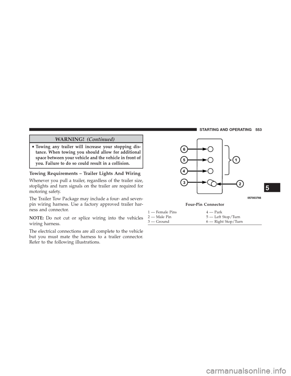
The electrical connections are all complete to the vehicle
but you must mate the harness to a trailer connector.
Refer to the following illustrations.
Four-Pin Connector
1 — Female Pins 4 — Park
2 — Male Pin 5 — Left Stop/Turn
3 — Ground 6 — Right Stop/Turn
5
STARTING AND OPERATING 553