Page 23 of 140

FRONT SEATS
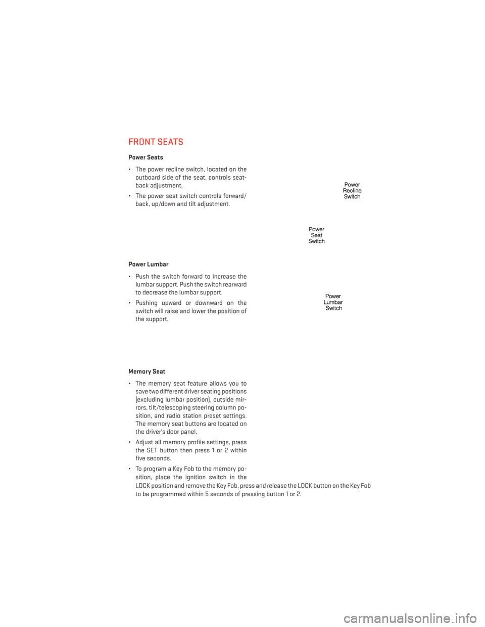
Power Seats
• The power recline switch, located on theoutboard side of the seat, controls seat-
back adjustment.
• The power seat switch controls forward/ back, up/down and tilt adjustment.
Power Lumbar
• Push the switch forward to increase the lumbar support. Push the switch rearward
to decrease the lumbar support.
• Pushing upward or downward on the switch will raise and lower the position of
the support.
Memory Seat
• The memory seat feature allows you to save two different driver seating positions
(excluding lumbar position), outside mir-
rors, tilt/telescoping steering column po-
sition, and radio station preset settings.
The memory seat buttons are located on
the driver's door panel.
• Adjust all memory profile settings, press the SET button then press 1 or 2 within
five seconds.
• To program a Key Fob to the memory po- sition, place the ignition switch in the
LOCK position and remove the Key Fob, press and release the LOCK button on the Key Fob
to be programmed within 5 seconds of pressing button 1 or 2.
GETTING STARTED
21
Page 24 of 140
• Place the ignition switch in the ON/RUN position, select Remote Linked to Memory in theElectronic Vehicle Information Center (EVIC) and enter Yes.
• Press 1 or 2 to recall the saved positions, or press UNLOCK on the programmed Key Fob.
• Refer to the Owner's Manual on the DVD for further details.
Manual Seat Adjustment
Forward/Rearward
• Lift up on the adjusting bar located at the front of the seat near the floor and release
it when the seat is at the desired position.
Then, using body pressure, move forward
and backward on the seat to be sure that
the seat adjusters have latched.
Recliner
• Lift the rear lever located on the outboardside of the seat, lean back and release
when seat is in desired position.
Fold-Flat Front Passenger Seat
• The front passenger seat can be folded flat to allow for extended cargo space.
Pull up on the recliner lever and fold the
seatback forward and down to a flat
position.
GETTING STARTED
22
Page 94 of 140

Shifting Into NEUTRAL
Use the following procedure to prepare your vehicle for recreational towing.
• Bring the vehicle to a complete stop and shift the transmission to PARK.
• Turn the engine off.
• For vehicles with Keyless Enter-N-Go, remove the Keyless Enter-N-Go button and use theKey Fob to complete this procedure.
• Turn the ignition switch to the ON/RUN position, but do not start the engine.
• Press and hold the brake pedal and shift the transmission into NEUTRAL.
• Press and hold the transfer case N (Neutral) button for four seconds, until the light next to the N symbol starts to blink, indicating shift in progress. The light will stop blinking
(stay on solid) when the shift to N (Neutral) is complete.
• Start the engine and shift the transmission into REVERSE.
• Release the brake pedal for five seconds and ensure that there is no vehicle movement.
• Turn the engine off and firmly apply the parking brake.
• Shift the transmission into PARK and remove the Key Fob.
• Attach the vehicle to the tow vehicle using a suitable tow bar and release the parking brake.
CAUTION!
•Towing with the rear wheels on the ground will cause severe transmission damage.
Damage from improper towing is not covered under the New Vehicle Limited Warranty.
• Front or rear wheel lifts should not be used. Internal damage to the transmission or
transfer case will occur if a front or rear wheel lift is used when recreational towing.
• It is necessary to follow these steps to be certain that the transfer case is fully in NEUTRAL before recreational towing to prevent damage to internal parts.
WARNING!
You or others could be injured if you leave the vehicle unattended with the transfer case
in the NEUTRAL position without first fully engaging the parking brake. The transfer case
NEUTRAL position disengages both the front and rear driveshafts from the powertrain
and will allow the vehicle to move even if the transmission is in PARK. The parking brake
should always be applied when the driver is not in the vehicle.
UTILITY
92
Page 130 of 140

WHEEL AND WHEEL TRIM CARE
• All wheels and wheel trim, especially aluminum and chrome plated wheels, should becleaned regularly with a mild soap and water to prevent corrosion.
• To remove heavy soil and/or excessive brake dust, use MOPAR® Wheel Cleaner or equivalent or select a non-abrasive, non-acidic cleaner.
CAUTION!
Do not use scouring pads, steel wool, a bristle brush, or metal polishes. Do not use oven
cleaner. These products may damage the wheel's protective finish. Avoid automatic car
washes that use acidic solutions or harsh brushes that may damage the wheel's protec-
tive finish. Only MOPAR® Wheel Cleaner or equivalent is recommended.
EXTERIOR BULBS
LIGHT BULBS – Exterior Bulb Number
Tail, Stop, Turn Lamp 3057
Backup Lamps 921 (W16W)
Center High-Mounted Stop Lamp (CHMSL) LED (*)
Fog Lamp – If Equipped PSX24W
Front Park/Turn Signal 7444NA
Front Side Marker Lamps W5W
License Lamp W5W
Headlamp – High Intensity Discharge (HID) Service at Authorized Dealer (**)
Headlamp – Low Beam H11
Headlamp – High Beam 9005
Liftgate Tail Lamps 194
* CHMSL is not serviceable. It is a LED lamp. To replace the LED, the entire CHMSL assembly
must be replaced.
** The headlamps are a type of high-voltage discharge tube. High voltage can remain in the
circuit even with the headlamp switch off and the Key Fob removed. Because of this, you
should not attempt to service a headlamp bulb yourself. If a headlamp bulb fails, take your
vehicle to an authorized dealer for service.
MAINTAINING YOUR VEHICLE
128
Page 135 of 140

FuelFiller Cap (Gas Cap) .........96
Filler Door Emergency Release . . .115
Specifications ..........118, 119
Gas Cap (Fuel Filler Cap) .........96
Headlights Automatic ..............29
Dimmer Switch ............30
HighBeam ..............31
High Beam/Low Beam Select
Switch ................31
Head Restraints Power Folding Third Row .......25
HeatedMirrors ..............37
High Beam/Low Beam Select (Dimmer) Switch ............31
HomeLink® (Garage Door Opener) ....82
Hood Release ..............114
Instrument Cluster Indicators ...............9
Instrument Cluster Warning Lights ....8
Integrated Power Module (Fuses) . . . .124
Intermittent Wipers (Delay Wipers) ....30
Introduction ................2
Inverter Outlet (115V) ...........84
Inverter,Power..............84
iPod®/USB/MP3 Control .........72
BluetoothStreamingAudio .....79
Jacking Instructions ...........101
Jack Location ..............98
Jack Operation ............98,101
JumpStarting..............107
KeyFob..................10
Keyless Enter-N-Go Lock/Unlock .............13
Starting/Stopping ..........15
Lane Change Assist ...........30
LATCH (Lower Anchors and Tether for CHildren)................18
Liftgate, Power ..............10
LightBulbs................128 Lights
Headlights ..............29
Warning (Instrument Cluster
Description) ..............8
Locks Liftgate, Tailgate ...........10
Luggage Rack (Roof Rack) ........89
Maintenance Record ...........123
Maintenance Schedule .........120
Malfunction Indicator Light (Check Engine) ............94
MemorySeat...............21
Mirrors Automatic Dimming .........31
Heated ................37
MOPAR® Accessories ..........131
Navigation Voice Prompt Volume. . .55, 65
New Vehicle Break-In Period .......29
Oil Change Indicator ...........96
Oil Change Indicator, Reset ........96
Oil, Engine Capacity .............. .118
Outlet Power.................85
Overheating, Engine ...........97
Park Sense System, Rear .........38
Placard, Tire and Loading Information. .127
Power Folding Third Row Head
Restraints ..............
25
Inverter ................84
Lift Gate ...............10
Outlet (Auxiliary Electrical Outlet) . .85
Seats .................21
Steering .............118, 119
Preparation for Jacking .........101
Programmable Electronic Features ....81
Rain Sensitive Wiper System .......30
RearCamera...............39
RearCrossPath .............39
Rear Heated Seats ............26
Rear Park Sense System .......38,39
INDEX
133