2013 DODGE DURANGO fuel
[x] Cancel search: fuelPage 98 of 140

Fuel Cap/Loose Gas Cap Message
• If a “gas cap” message (shown as Check Gascap) appears, tighten the gas cap until a“clicking” sound is heard.
• If the message continues to appear for more than three days after tightening the gas cap, have the vehicle serviced by an authorized service center immediately.
Oil Change Indicator
• Your vehicle is equipped with an engine oil change indicator system. The “Oil Change Due” message will flash in the EVIC display for approximately 10 seconds after a single
chime has sounded, to indicate the next scheduled oil change interval. The engine oil
change indicator system is duty cycle based, which means the engine oil change interval
may fluctuate, dependent upon your personal driving style
• Unless reset, this message will continue to display each time you turn the ignition switch to the ON/RUN position or cycle the ignition to the ON/RUN position if equipped with
Keyless Enter-N-Go™. To turn off the message temporarily, press and release the MENU
button. To reset the oil change indicator system (after performing the scheduled main-
tenance) refer to the following procedure.
Vehicles Equipped With Keyless Enter-N-Go™
1. Without pressing the brake pedal, cycle the ignition to the ON/RUN position (Do not start the engine).
2. Fully depress the accelerator pedal, slowly, three times within 10 seconds.
3. Cycle the ignition to the OFF/LOCK position.
Vehicles Not Equipped With Keyless Enter-N-Go™
1. Turn the ignition switch to the ON/RUN position (Do not start the engine).
2. Fully depress the accelerator pedal, slowly, three times within 10 seconds.
3. Turn the ignition switch to the OFF/LOCK position.
NOTE:
If the indicator message illuminates when you start the vehicle, the oil change indicator
system did not reset. If necessary, repeat this procedure.
Resetting The Light After Servicing
Vehicles Equipped With Keyless Enter-N-Go™
• Without pressing the brake pedal, push the ENGINE START/STOP button and cycle the ignition to the ON/RUN position (Do not start the engine.)
• Fully depress the accelerator pedal, slowly, three times within 10 seconds.
• Without pressing the brake pedal, push the ENGINE START/STOP button once to return the ignition to the OFF/LOCK position.
WHAT TO DO IN EMERGENCIES
96
Page 116 of 140

OPENING THE HOOD
•Pull the hood release lever located below
the steering wheel at the base of the instru-
ment panel.
•Reach into the opening beneath the center
of the hood and move the safety latch lever
while lifting the hood at the same time.
WARNING!
Be sure the hood is fully latched before driving your vehicle. If the hood is not fully
latched, it could open when the vehicle is in motion and block your vision. Failure to
follow this warning could result in serious injury or death.
FUEL DOOR RELEASE
• The fuel door release button is located on the instrument panel below the headlight
switch.
• Push the button once and release to open the fuel door.
MAINTAINING YOUR VEHICLE
114
Page 117 of 140

Fuel Door Emergency Release
• To manually open the fuel door, removethe storage bin located in the left rear
cargo area.
•
Pull the release cable located in the storage
bin opening.
MAINTAINING YOUR VEHICLE
115
Page 121 of 140

Component Fluid, Lubricant, or Genuine PartCapacities
Power Steering Reservoir –
3.6L Engine We recommend you use MOPAR® Hydraulic
Fluid meeting Chrysler Material Standard MS-11655. —
Power Steering Reservoir –
5.7L Engine We recommend you use MOPAR® Power
Steering Fluid +4, or MOPAR® ATF+4®
Automatic Transmission Fluid meeting Chrysler Material Standard MS-9602. —
Fuel Selection –
3.6L, 5.7L Engine 87 Octane acceptable. 89 Octane
recommended for 5.7L. 25 Gallons (94 Liters)
(Approximate)
CAUTION!
• Mixing of engine coolant (antifreeze) other than specified Organic Additive Technol-
ogy (OAT) engine coolant (antifreeze), may result in engine damage and may de-
crease corrosion protection. Organic Additive Technology (OAT) engine coolant is
different and should not be mixed with Hybrid Organic Additive Technology (HOAT)
engine coolant (antifreeze) or any “globally compatible” coolant (antifreeze). If a
non-OAT engine coolant (antifreeze) is introduced into the cooling system in an
emergency, it should be flushed with OAT coolant and replaced with the specified
OAT engine coolant (antifreeze) as soon as possible.
• Do not use water alone or alcohol-based engine coolant (antifreeze) products. Do not
use additional rust inhibitors or antirust products, as they may not be compatible
with the radiator engine coolant and may plug the radiator.
• This vehicle has not been designed for use with propylene glycol-based engine
coolant (antifreeze). Use of propylene glycol-based engine coolant (antifreeze) is not
recommended.
E-85 Flexible Fuel – 3.6L Engine Only
CAUTION!
Only vehicles with the E-85 fuel filler door label or a yellow gas cap can operate on E-85.
• Refer to your Owner's Manual on the DVD for further details.
MAINTAINING YOUR VEHICLE
119
Page 122 of 140

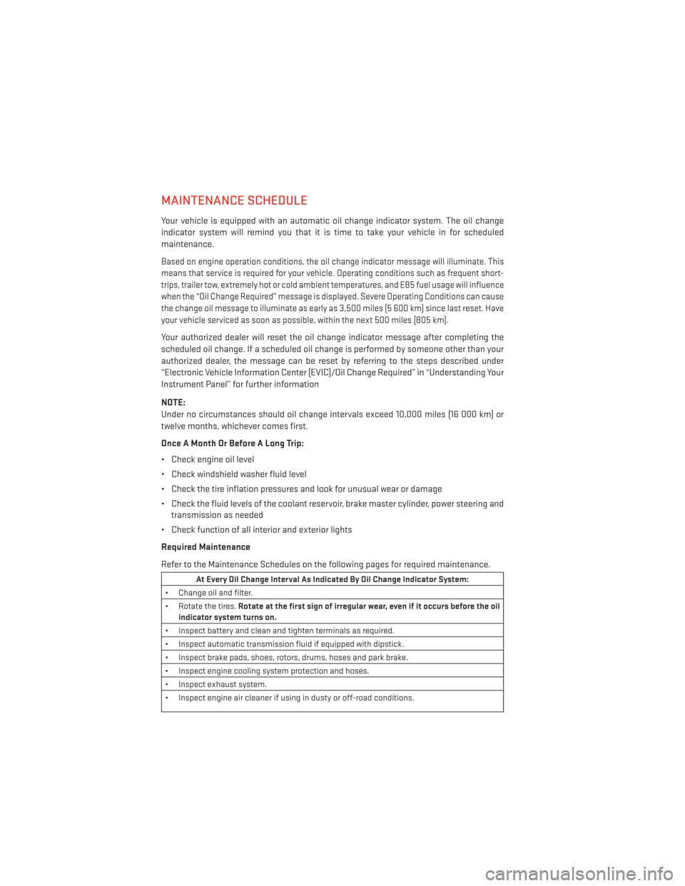
MAINTENANCE SCHEDULE
Your vehicle is equipped with an automatic oil change indicator system. The oil change
indicator system will remind you that it is time to take your vehicle in for scheduled
maintenance.
Based on engine operation conditions, the oil change indicator message will illuminate. This
means that service is required for your vehicle. Operating conditions such as frequent short-
trips, trailer tow, extremely hot or cold ambient temperatures, and E85 fuel usage will influence
when the “Oil Change Required” message is displayed. Severe Operating Conditions can cause
the change oil message to illuminate as early as 3,500 miles (5 600 km) since last reset. Have
your vehicle serviced as soon as possible, within the next 500 miles (805 km).
Your authorized dealer will reset the oil change indicator message after completing the
scheduled oil change. If a scheduled oil change is performed by someone other than your
authorized dealer, the message can be reset by referring to the steps described under
“Electronic Vehicle Information Center (EVIC)/Oil Change Required” in “Understanding Your
Instrument Panel” for further information
NOTE:
Under no circumstances should oil change intervals exceed 10,000 miles (16 000 km) or
twelve months, whichever comes first.
Once A Month Or Before A Long Trip:
• Check engine oil level
• Check windshield washer fluid level
• Check the tire inflation pressures and look for unusual wear or damage
• Check the fluid levels of the coolant reservoir, brake master cylinder, power steering andtransmission as needed
• Check function of all interior and exterior lights
Required Maintenance
Refer to the Maintenance Schedules on the following pages for required maintenance.
At Every Oil Change Interval As Indicated By Oil Change Indicator System:
• Change oil and filter.
• Rotate the tires. Rotate at the first sign of irregular wear, even if it occurs before the oil
indicator system turns on.
• Inspect battery and clean and tighten terminals as required.
• Inspect automatic transmission fluid if equipped with dipstick.
• Inspect brake pads, shoes, rotors, drums, hoses and park brake.
• Inspect engine cooling system protection and hoses.
• Inspect exhaust system.
• Inspect engine air cleaner if using in dusty or off-road conditions.
MAINTAINING YOUR VEHICLE
120
Page 128 of 140

Cavity Cartridge Fuse Mini FuseDescription
M13 20 Amp Yellow Instrument Cluster/Ignition Module
M14 20 Amp Yellow Back Up Camera
M15 20 Amp Yellow Power Seat Module(s)/Adaptive Cruise
Control/Audio Telematics/Daytime Running
Lights Relay/Instrument Cluster
M16 10 Amp Red Occupant Restraint Controller
M18 15 Amp Blue Stop Lamp
M19 25 Amp Natural Automatic Shutdown 1 and 2
M20 15 Amp Blue Instrument Cluster/Steering Wheel Switches
M21 20 Amp Yellow Automatic Shutdown 3
M22 10 Amp Red Horns (Low/High) – Right
M23 10 Amp Red Horns (Low/High) – Left
M24 25 Amp Natural Rear Wiper
M25 20 Amp Yellow Fuel Pump Motor Output
M26 10 Amp Red Switch Bank/Interior Lighting
M27 10 Amp Red Ignition Switch/Wireless Control Module/
Keyless Entry Module
M28 15 Amp Blue
Powertrain Controller/Transmission Controller
M2910 Amp Red Tire Pressure Monitor
M30 15 Amp Blue J1962 Diag Connector
M31 20 Amp Yellow Backup Lamps
M32 10 Amp Red Occupant Restraint Controller
M33 10 Amp Red
Powertrain Controller/Transmission Controller
M3410 Amp Red Park Assist Module/Climate Control System
Module/IR Sensor/Compass Module
M35 15 Amp Blue LH Rear Parklamps
M36 20 Amp Yellow Power Outlet
M37 10 Amp Red Antilock Brakes/Stability Control System
Module/Stoplamp Switch Sensor
M38 25 Amp Natural All Door Lock &Unlock
CAUTION!
• When installing the integrated power module cover, it is important to ensure the
cover is properly positioned and fully latched. Failure to do so may allow water to get
into the integrated power module, and possibly result in a electrical system failure.
• When replacing a blown fuse, it is important to use only a fuse having the correct
amperage rating. The use of a fuse with a rating other than indicated may result in a
dangerous electrical system overload. If a properly rated fuse continues to blow, it
indicates a problem in the circuit that must be corrected.
MAINTAINING YOUR VEHICLE
126
Page 135 of 140

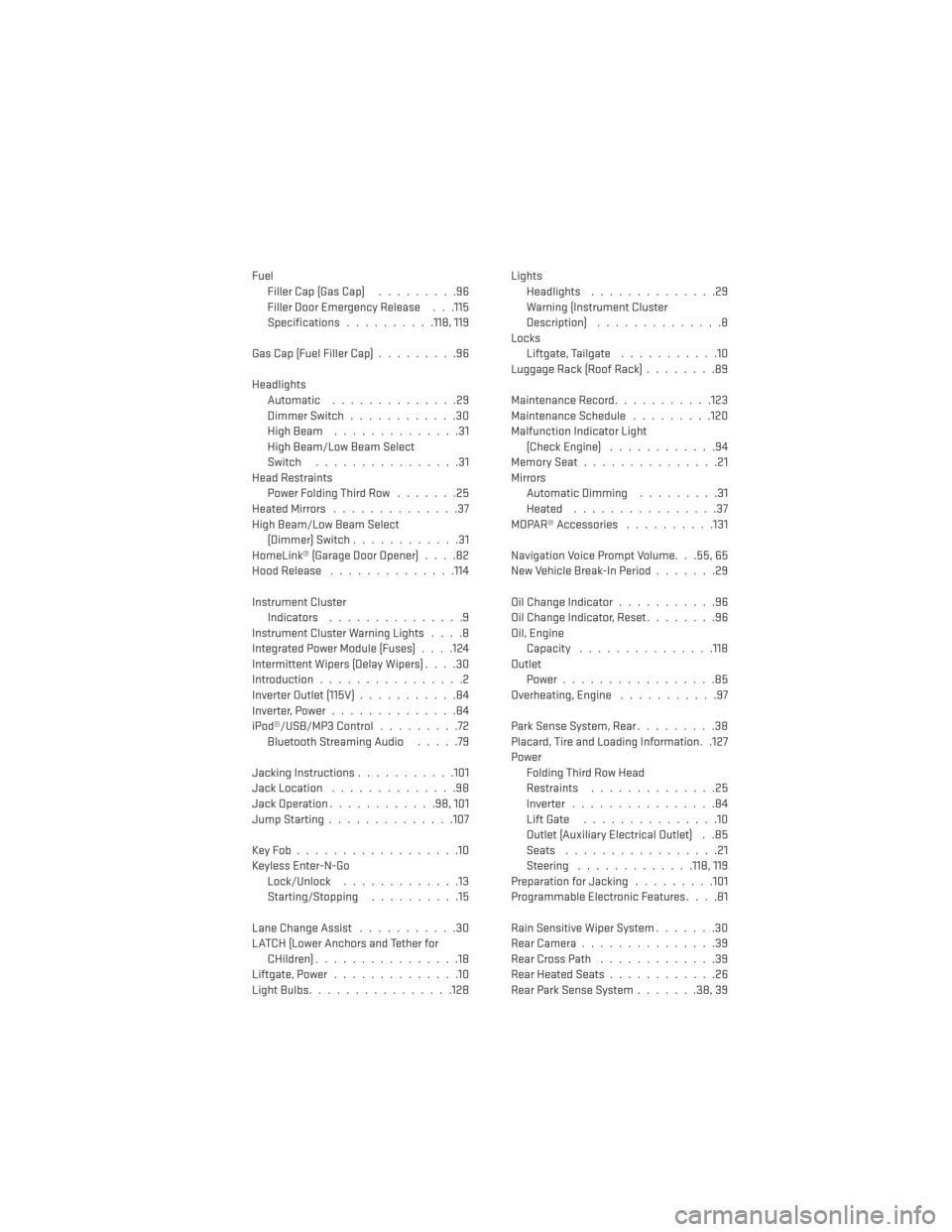
FuelFiller Cap (Gas Cap) .........96
Filler Door Emergency Release . . .115
Specifications ..........118, 119
Gas Cap (Fuel Filler Cap) .........96
Headlights Automatic ..............29
Dimmer Switch ............30
HighBeam ..............31
High Beam/Low Beam Select
Switch ................31
Head Restraints Power Folding Third Row .......25
HeatedMirrors ..............37
High Beam/Low Beam Select (Dimmer) Switch ............31
HomeLink® (Garage Door Opener) ....82
Hood Release ..............114
Instrument Cluster Indicators ...............9
Instrument Cluster Warning Lights ....8
Integrated Power Module (Fuses) . . . .124
Intermittent Wipers (Delay Wipers) ....30
Introduction ................2
Inverter Outlet (115V) ...........84
Inverter,Power..............84
iPod®/USB/MP3 Control .........72
BluetoothStreamingAudio .....79
Jacking Instructions ...........101
Jack Location ..............98
Jack Operation ............98,101
JumpStarting..............107
KeyFob..................10
Keyless Enter-N-Go Lock/Unlock .............13
Starting/Stopping ..........15
Lane Change Assist ...........30
LATCH (Lower Anchors and Tether for CHildren)................18
Liftgate, Power ..............10
LightBulbs................128 Lights
Headlights ..............29
Warning (Instrument Cluster
Description) ..............8
Locks Liftgate, Tailgate ...........10
Luggage Rack (Roof Rack) ........89
Maintenance Record ...........123
Maintenance Schedule .........120
Malfunction Indicator Light (Check Engine) ............94
MemorySeat...............21
Mirrors Automatic Dimming .........31
Heated ................37
MOPAR® Accessories ..........131
Navigation Voice Prompt Volume. . .55, 65
New Vehicle Break-In Period .......29
Oil Change Indicator ...........96
Oil Change Indicator, Reset ........96
Oil, Engine Capacity .............. .118
Outlet Power.................85
Overheating, Engine ...........97
Park Sense System, Rear .........38
Placard, Tire and Loading Information. .127
Power Folding Third Row Head
Restraints ..............
25
Inverter ................84
Lift Gate ...............10
Outlet (Auxiliary Electrical Outlet) . .85
Seats .................21
Steering .............118, 119
Preparation for Jacking .........101
Programmable Electronic Features ....81
Rain Sensitive Wiper System .......30
RearCamera...............39
RearCrossPath .............39
Rear Heated Seats ............26
Rear Park Sense System .......38,39
INDEX
133