Page 502 of 604

Sealing A Tire With TIREFIT
(A) Whenever You Stop To Use TIREFIT:
1. Pull over to a safe location and turn on the vehicle’s
Hazard Warning flashers.
2. Verify that the valve stem (on the wheel with the
deflated tire) is in a position that is near to the ground.
This will allow the TIREFIT Hoses (6) and (7) to reach the
valve stem and keep the TIREFIT kit flat on the ground.
This will provide the best positioning of the kit when
injecting the sealant into the deflated tire and running the
air pump. Move the vehicle as necessary to place the
valve stem in this position before proceeding.
3. Place the transmission in PARK (auto transmission) or
in Gear (manual transmission) and turn Off the ignition.
4. Set the parking brake.
(B) Setting Up To Use TIREFIT:
1. Turn the Mode Select Knob (5) to the Sealant Mode
position.
2. Uncoil the Sealant Hose (6) and then remove the cap
from the fitting at the end of the hose.
3. Place the TIREFIT kit flat on the ground next to the
deflated tire.
4. Remove the cap from the valve stem and then screw
the fitting at the end of the Sealant Hose (6) onto the
valve stem.
5. Uncoil the Power Plug (8) and insert the plug into the
vehicle’s 12 Volt power outlet.
NOTE:Do not remove foreign objects (e.g., screws or
nails) from the tire.
500 WHAT TO DO IN EMERGENCIES
Page 505 of 604

CAUTION!
•The metal end fitting from Power Plug (8) may get
hot after use, so it should be handled carefully.
•Failure to reinstall the cap on the fitting at the end
of the Sealant Hose (6) can result in sealant con-
tacting your skin, clothing, and the vehicle’s inte-
rior. It can also result in sealant contacting internal
TIREFIT kit components which may cause perma-
nent damage to the kit.
(D) Drive Vehicle:
Immediately after injecting sealant and inflating the tire,
drive the vehicle 5 miles (8 km) or 10 minutes to ensure
distribution of the TIREFIT Sealant within the tire. Do not
exceed 55 mph (88 km/h).
WARNING!
TIREFIT is not a permanent flat tire repair. Have the
tire inspected and repaired or replaced after using
TIREFIT. Do not exceed 55 mph (88 km/h) until the
tire is repaired or replaced. Failure to follow this
warning can result in injuries that are serious or fatal
to you, your passengers, and others around you.
(E) After Driving:
Pull over to a safe location. Refer to “Whenever You Stop
to Use TIREFIT” before continuing.
1. Turn the Mode Select Knob (5) to the Air Mode
position.
2. Uncoil the power plug and insert the plug into the
vehicle’s 12 Volt power outlet.
6
WHAT TO DO IN EMERGENCIES 503
Page 506 of 604

3. Uncoil the Air Pump Hose (7) (black in color) and
screw the fitting at the end of hose (7) onto the valve
stem.
4. Check the pressure in the tire by reading the Pressure
Gauge (3).
If tire pressure is less than 19 psi (1.3 Bar), the tire is too
badly damaged. Do not attempt to drive the vehicle
further. Call for assistance.
If the tire pressure is 19 psi (1.3 bar) or higher:
1. Press the Power Button (4) to turn on TIREFIT and
inflate the tire to the pressure indicated on the tire and
loading information label on the driver-side door open-
ing.
NOTE: If the tire becomes over-inflated, press the
Deflation Button to reduce the tire pressure to the recom-
mended inflation pressure before continuing. 2. Disconnect the TIREFIT kit from the valve stem,
reinstall the cap on the valve stem and unplug from 12
Volt outlet.
3. Place the TIREFIT kit in its proper storage area in the
vehicle.
4. Have the tire inspected and repaired or replaced at the
earliest opportunity at an authorized dealer or tire ser-
vice center.
5. Replace the Sealant Bottle (1) and Sealant Hose (6)
assembly at your authorized dealer as soon as possible.
Refer to “(F) Sealant Bottle and Hose Replacement.”
NOTE:
When having the tire serviced, advise the au-
thorized dealer or service center that the tire has been
sealed using the TIREFIT service kit.
(F) Sealant Bottle And Hose Replacement:
1. Uncoil the Sealant Hose (6) (clear in color).
504 WHAT TO DO IN EMERGENCIES
Page 555 of 604
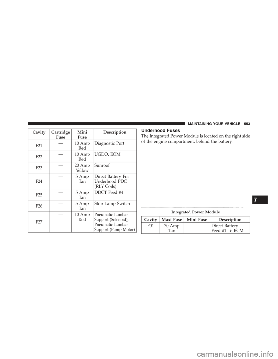
Cavity CartridgeFuseMini
Fuse Description
F21 — 10 Amp
RedDiagnostic Port
F22 — 10 Amp
RedUGDO, EOM
F23 — 20 Amp
Yellow Sunroof
F24 — 5 Amp
Ta nDirect Battery For
Underhood PDC
(RLY Coils)
F25 — 5 Amp
Ta nDDCT Feed #4
F26 — 5 Amp
Ta nStop Lamp Switch
F27 — 10 Amp
Red
Pneumatic Lumbar
Support (Solenoid),
Pneumatic Lumbar
Support (Pump Motor)
Underhood Fuses
The Integrated Power Module is located on the right side
of the engine compartment, behind the battery.
Cavity Maxi Fuse Mini Fuse Description
F01 70 Amp Ta n — Direct Battery
Feed #1 To BCM
Integrated Power Module
7
MAINTAINING YOUR VEHICLE 553
Page 556 of 604
Cavity Maxi Fuse Mini Fuse DescriptionF02 60 Amp Blue — Direct Battery
Feed #2 To BCM
F03 30 Amp Green — Output For Starter
Relay #1
F04 40 Amp Orange — ESP Pump Motor
F05 40 Amp Orange — DDCT Feed #1
(SDU)
F06 30 Amp Green — Direct Battery
Feed #3 To BCM
F07 40 Amp Orange — EBL RLY Coil,
Blower Motor RLY
Coil
F09 — 5 Amp Tan Radiator Fan En- able RLY, Radiator
Fan Enable RLY
CoilCavity Maxi Fuse Mini Fuse Description
F10 — 10 Amp RedORC
F11 — 20 Amp YellowECM, EPS, Backup
Lamp Switch
F14 — 15 Amp BlueDDCT Feed #2
F15 — 15 Amp BlueDDCT Feed #3
F16 — 15 Amp BlueIgnition Coils, Coil
Capacitor
F17 — 15 Amp BlueESC, Brake Pedal
Switch, OCM
F18 — 20 Amp YellowECM
F19 — 10 Amp RedA/C Compressor
Clutch
554 MAINTAINING YOUR VEHICLE