Page 241 of 599

NOTE:
•The vehicle should be traveling at a steady speed and
on level ground before pressing the SET button.
• The Electronic Speed Control may not engage if a
different size tire is installed on one wheel, such as the
compact spare tire (if equipped).
To Deactivate
A soft tap on the brake pedal, pushing the CANCEL
button, or normal brake pressure while slowing the
vehicle will deactivate Electronic Speed Control without
erasing the set speed memory. Pressing the ON/OFF
button or turning the ignition switch OFF erases the set
speed memory.
To Resume Speed
To resume a previously set speed, push the RES (+)
button and release. Resume can be used at any speed
above 20 mph (32 km/h).
To Vary The Speed Setting
When the Electronic Speed Control is set, you can in-
crease speed by pushing the RES (+) button. If the button
is continually pressed, the set speed will continue to
increase until the button is released, then the new set
speed will be established.
Pressing the RES (+) button once will result ina1mph
(1.6 km/h) increase in set speed. Each subsequent tap of
the button results in an increase of 1 mph (1.6 km/h).
3
UNDERSTANDING THE FEATURES OF YOUR VEHICLE 239
Page 315 of 599

As an added safety feature")
a different size than the size indicated on the vehicle
placard or tire inflation pressure label, you should deter-
mine the proper tire inflation pressure for those tires.)
As an added safety feature, your vehicle has been
equipped with a Tire Pressure Monitoring System
(TPMS) that illuminates a low tire pressure telltale when
one or more of your tires is significantly under-inflated.
Accordingly, when the low tire pressure telltale illumi-
nates, you should stop and check your tires as soon as
possible, and inflate them to the proper pressure. Driving
on a significantly under-inflated tire causes the tire to
overheat and can lead to tire failure. Under-inflation also
reduces fuel efficiency and tire tread life, and may affect
the vehicle’s handling and stopping ability.
Please note that the TPMS is not a substitute for proper
tire maintenance, and it is the driver ’s responsibility to
maintain correct tire pressure, even if under-inflation has
not reached the level to trigger illumination of the TPMS
low tire pressure telltale.Your vehicle has also been equipped with a TPMS
malfunction indicator to indicate when the system is not
operating properly. The TPMS malfunction indicator is
combined with the low tire pressure telltale. When the
system detects a malfunction, the telltale will flash for
approximately one minute and then remain continuously
illuminated. This sequence will continue upon subse-
quent vehicle start-ups as long as the malfunction exists.
When the malfunction indicator is illuminated, the sys-
tem may not be able to detect or signal low tire pressure
as intended. TPMS malfunctions may occur for a variety
of reasons, including the installation of replacement or
alternate tires or wheels on the vehicle that prevent the
TPMS from functioning properly. Always check the
TPMS malfunction telltale after replacing one or more
tires or wheels on your vehicle, to ensure that the
replacement or alternate tires and wheels allow the TPMS
to continue to function properly.
4
UNDERSTANDING YOUR INSTRUMENT PANEL 313
Page 316 of 599

CAUTION!
The TPMS has been optimized for the original
equipment tires and wheels. TPMS pressures and
warning have been established for the tire size
equipped on your vehicle. Undesirable system opera-
tion or sensor damage may result when using re-
placement equipment that is not of the same size,
type, and/or style. Aftermarket wheels can cause
sensor damage. Do not use tire sealant from a can or
balance beads if your vehicle is equipped with a
TPMS, as damage to the sensors may result.
8. Malfunction Indicator Light (MIL) The Malfunction Indicator Light (MIL) is part of
an onboard diagnostic system, called OBD, that
monitors engine and automatic transmission con-
trol systems. The light will illuminate when the key is in the ON/RUN position, before engine start. If the bulb
does not come on when turning the key from OFF to
ON/RUN, have the condition checked promptly.
Certain conditions, such as poor fuel quality, etc., may
illuminate the MIL after engine start. The vehicle should
be serviced if the light stays on through several of your
typical driving cycles. In most situations, the vehicle will
drive normally and will not require towing.
CAUTION!
Prolonged driving with the Malfunction Indicator
Light (MIL) on could cause damage to the engine
control system. It also could affect fuel economy and
drivability. If the MIL is flashing, severe catalytic
converter damage and power loss will soon occur.
Immediate service is required.
314 UNDERSTANDING YOUR INSTRUMENT PANEL
Page 419 of 599

These are all normal characteristics of ABS.
WARNING!
•The ABS contains sophisticated electronic equip-
ment that may be susceptible to interference
caused by improperly installed or high output
radio transmitting equipment. This interference
can cause possible loss of anti-lock braking capa-
bility. Installation of such equipment should be
performed by qualified professionals.
• Pumping of the Anti-Lock Brakes will diminish
their effectiveness and may lead to a collision.
Pumping makes the stopping distance longer. Just
press firmly on your brake pedal when you need to
slow down or stop.
(Continued)
WARNING! (Continued)
•The ABS cannot prevent the natural laws of phys-
ics from acting on the vehicle, nor can it increase
braking or steering efficiency beyond that afforded
by the condition of the vehicle brakes and tires or
the traction afforded.
• The ABS cannot prevent collisions, including those
resulting from excessive speed in turns, following
another vehicle too closely, or hydroplaning.
• The capabilities of an ABS equipped vehicle must
never be exploited in a reckless or dangerous
manner that could jeopardize the user’s safety or
the safety of others.
All vehicle wheels and tires must be the same size and
type and tires must be properly inflated to produce
accurate signals for the computer.
5
STARTING AND OPERATING 417
Page 429 of 599
The “ESC OFF Indicator Light” indicates the
Electronic Stability Control (ESC) is off.
Synchronizing ESC
If the power supply is interrupted (battery
disconnected or discharged), the “ESC
Activation/Malfunction Indicator Light” may
illuminate with the engine running. If this
should occur, turn the steering wheel completely to the
left and then to the right. The “ESC Activation/
Malfunction Indicator Light” should go out. However, if
the light remains on, have the ESC and BAS checked at
your authorized dealer as soon as possible.
TIRE SAFETY INFORMATION
Tire Markings
1 — U.S. DOT Safety
Standards Code (TIN) 4 — Maximum Load
2 — Size Designation 5 — Maximum Pressure
3 — Service Description 6 — Treadwear, Traction and
Temperature Grades
5
STARTING AND OPERATING 427
Page 430 of 599
 - Metric tire sizing is based on U.S.
design standards. P-Metric tires have the letter “P”
molded into the sidewall preceding the size designa-
tion. Example: P215/65R15 95H")
NOTE:
•P (Passenger) - Metric tire sizing is based on U.S.
design standards. P-Metric tires have the letter “P”
molded into the sidewall preceding the size designa-
tion. Example: P215/65R15 95H.
• European-Metric tire sizing is based on European
design standards. Tires designed to this standard have
the tire size molded into the sidewall beginning with
the section width. The letter �P�is absent from this tire
size designation. Example: 215/65R15 96H. •
LT (Light Truck) - Metric tire sizing is based on U.S.
design standards. The size designation for LT-Metric
tires is the same as for P-Metric tires except for the
letters “LT” that are molded into the sidewall preced-
ing the size designation. Example: LT235/85R16.
• Temporary spare tires are spares designed for tempo-
rary emergency use only. Temporary high pressure
compact spare tires have the letter “T” or “S” molded
into the sidewall preceding the size designation. Ex-
ample: T145/80D18 103M.
• High flotation tire sizing is based on U.S. design
standards and it begins with the tire diameter molded
into the sidewall. Example: 31x10.5 R15 LT.
428 STARTING AND OPERATING
Page 431 of 599
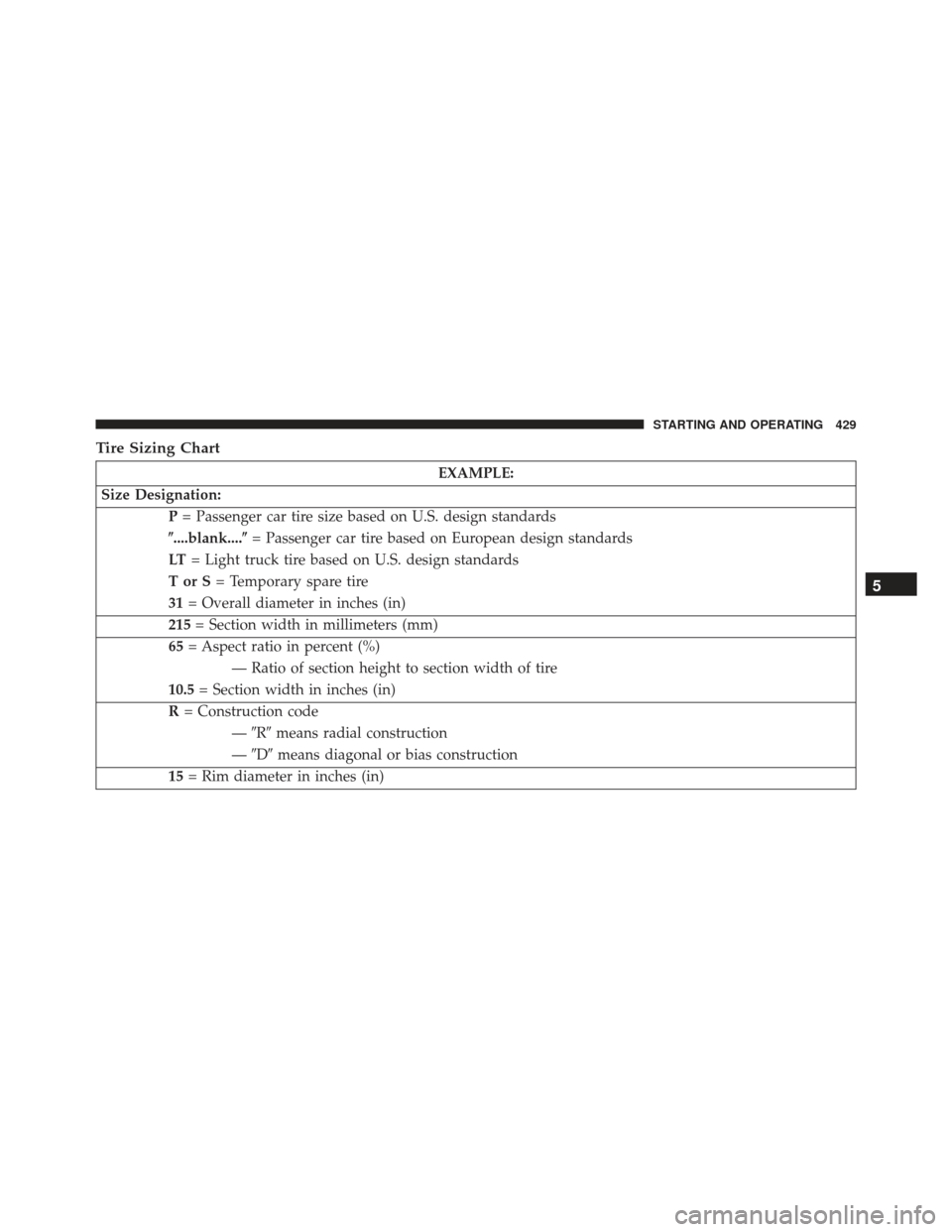
Tire Sizing Chart
EXAMPLE:
Size Designation: P= Passenger car tire size based on U.S. design standards
�....blank....� = Passenger car tire based on European design standards
LT = Light truck tire based on U.S. design standards
TorS= Temporary spare tire
31 = Overall diameter in inches (in)
215 = Section width in millimeters (mm)
65 = Aspect ratio in percent (%)
— Ratio of section height to section width of tire
10.5 = Section width in inches (in)
R = Construction code
—�R� means radial construction
— �D� means diagonal or bias construction
15 = Rim diameter in inches (in)
5
STARTING AND OPERATING 429
Page 433 of 599
Tire Identification Number (TIN)
The TIN may be found on one or both sides of the tire,
however, the date code may only be on one side. Tires
with white sidewalls will have the full TIN, including the
date code, located on the white sidewall side of the tire.Look for the TIN on the outboard side of black sidewall
tires as mounted on the vehicle. If the TIN is not found on
the outboard side, then you will find it on the inboard
side of the tire.
EXAMPLE:
DOT MA L9 ABCD 0301
DOT = Department of Transportation
— This symbol certifies that the tire is in compliance with the U.S. Department of Transportation tire
safety standards and is approved for highway use
MA = Code representing the tire manufacturing location (two digits)
L9 = Code representing the tire size (two digits)
ABCD = Code used by the tire manufacturer (one to four digits)
03 = Number representing the week in which the tire was manufactured (two digits)
— 03 means the 3rd week5
STARTING AND OPERATING 431
 is off.
Synchronizing ESC
If the power supply is interrupted (battery
disconnected or discharged), the “ESC
Activat")

The TIN may be found on one or both sides of the tire,
however, the date code may only be on one side. Tires
with white sidewalls will have the full TIN, including the")