Page 104 of 631
Periodic Safety Checks You Should Make Outside
The Vehicle
Tires
Examine tires for excessive tread wear and uneven wear
patterns. Check for stones, nails, glass, or other objects
lodged in the tread or sidewall. Inspect the tread for cuts
and cracks. Inspect sidewalls for cuts, cracks and bulges.
Check the wheel nuts for tightness. Check the tires
(including spare) for proper cold inflation pressure.
Lights
Have someone observe the operation of brake lights and
exterior lights while you work the controls. Check turn
signal and high beam indicator lights on the instrument
panel.
Door Latches
Check for positive closing, latching, and locking.
Fluid Leaks
Check area under vehicle after overnight parking for fuel,
engine coolant, oil, or other fluid leaks. Also, if gasoline
fumes are detected or if fuel, power steering fluid, or
brake fluid leaks are suspected, the cause should be
located and corrected immediately.
102 THINGS TO KNOW BEFORE STARTING YOUR VEHICLE
Page 244 of 631

WARNING!
Leaving the Electronic Speed Control system on
when not in use is dangerous. You could accidentally
set the system or cause it to go faster than you want.
You could lose control and have an accident. Always
leave the system OFF when you are not using it.
To Set A Desired Speed
Turn the Electronic Speed Control ON. When the vehicle
has reached the desired speed, press the SET (-) button
and release. Release the accelerator and the vehicle will
operate at the selected speed.NOTE:
•
The vehicle should be traveling at a steady speed and
on level ground before pressing the SET button.
• The Electronic Speed Control may not engage if a
different size tire is installed on one wheel, such as the
compact spare tire (if equipped).
To Deactivate
A soft tap on the brake pedal, pushing the CANCEL
button, or normal brake pressure while slowing the
vehicle will deactivate Electronic Speed Control without
erasing the set speed memory. Pressing the ON/OFF
button or turning the ignition switch OFF erases the set
speed memory.
242 UNDERSTANDING THE FEATURES OF YOUR VEHICLE
Page 320 of 631
,
should be checked monthly when cold and in-
flated to the inflation pressure recommended by
the")
8. Tire Pressure Monitoring Telltale Light — If Equipped
Each tire, including the spare (if provided),
should be checked monthly when cold and in-
flated to the inflation pressure recommended by
the vehicle manufacturer on the vehicle placard
or tire inflation pressure label. (If your vehicle has tires of
a different size than the size indicated on the vehicle
placard or tire inflation pressure label, you should deter-
mine the proper tire inflation pressure for those tires.)
As an added safety feature, your vehicle has been equipped
with a Tire Pressure Monitoring System (TPMS) that illumi-
nates a low tire pressure telltale when one or more of your
tires is significantly under-inflated. Accordingly, when the
low tire pressure telltale illuminates, you should stop and
check your tires as soon as possible, and inflate them to the
proper pressure. Driving on a significantly under-inflated
tire causes the tire to overheat and can lead to tire failure.
Under-inflation also reduces fuel efficiency and tire tread
life, and may affect the vehicle’s handling and stopping
ability.
Please note that the TPMS is not a substitute for proper
tire maintenance, and it is the driver ’s responsibility to
maintain correct tire pressure, even if under-inflation has
not reached the level to trigger illumination of the TPMS
low tire pressure telltale.
Your vehicle has also been equipped with a TPMS
malfunction indicator to indicate when the system is not
operating properly. The TPMS malfunction indicator is
combined with the low tire pressure telltale. When the
system detects a malfunction, the telltale will flash for
approximately one minute and then remain continuously
illuminated. This sequence will continue upon subse-
quent vehicle start-ups as long as the malfunction exists.
When the malfunction indicator is illuminated, the sys-
tem may not be able to detect or signal low tire pressure
as intended. TPMS malfunctions may occur for a variety
of reasons, including the installation of replacement or
alternate tires or wheels on the vehicle that prevent the
TPMS from functioning properly. Always check the
318 UNDERSTANDING YOUR INSTRUMENT PANEL
Page 341 of 631

Press and release the UP or DOWN button until “Vehicle
Info” displays in the EVIC and press the SELECT button.
Press the UP and DOWN button to scroll t")
Vehicle Info (Customer Information Features)
Press and release the UP or DOWN button until “Vehicle
Info” displays in the EVIC and press the SELECT button.
Press the UP and DOWN button to scroll through the
available information displays, then press SELECT to
display any one of the following choices.
•Coolant Temp
Displays the actual coolant temperature.
• Oil Temperature
Displays the actual oil temperature.
• Oil Pressure
Displays the actual oil pressure.
• Trans Temperature
Displays the actual transmission temperature. •
Engine Hours
Displays the number of hours of engine operation.
• Tire Pressure
Shows the actual tire pressure for each tire (EXCLUDING
THE SPARE TIRE).
Messages #
Select from Main Menu using the UP or DOWN buttons.
This feature shows the number of stored warning messages
(in the # place holder). Pressing the SELECT button will
allow you to see what the stored messages are. Pressing the
BACK button takes you back to the Main Menu.
Turn Menu OFF
Select from Main Menu using the DOWN button. Press-
ing the SELECT button blanks the menu display. Pressing
any one of the four steering wheel buttons brings the
menu back.
4
UNDERSTANDING YOUR INSTRUMENT PANEL 339
Page 393 of 631
 ...........445
▫ Tire Terminology And Definitions ..........447
▫ Tire")
�TIRE SAFETY INFORMATION .............441
▫ Tire Markings ....................... .441
▫ Tire Identification Number (TIN) ...........445
▫ Tire Terminology And Definitions ..........447
▫ Tire Loading And Tire Pressure ...........448
� TIRES — GENERAL INFORMATION .........452
▫ Tire Pressure ....................... .452
▫ Tire Inflation Pressures .................453
▫ Tire Pressures For High Speed Operation . . . .455
▫ Radial Ply Tires ..................... .455
▫ Tire Types .......................... .456
▫ Run Flat Tires ....................... .457
▫ Spare Tires ......................... .457▫
Tire Spinning ....................... .460
▫ Tread Wear Indicators ..................460
▫ Life Of Tire ........................ .461
▫ Replacement Tires .....................461
� TIRE CHAINS ........................ .463
� TIRE ROTATION RECOMMENDATIONS .....465
� TIRE PRESSURE MONITOR SYSTEM (TPMS) . .466
▫ Base System ........................ .468
▫ Premium System – If Equipped ............471
▫ General Information ...................476
� FUEL REQUIREMENTS ..................476
▫ 3.6L Engine – If Equipped ...............476
▫ 5.7L Engine – If Equipped ...............476
5
STARTING AND OPERATING 391
Page 444 of 631
 - Metric tire sizing is based on U.S.
design standards. P-Metric tires have the letter “P”
molded into the sidewall preceding the size designa-
tion. Example: P215/65R15 95H")
NOTE:
•P (Passenger) - Metric tire sizing is based on U.S.
design standards. P-Metric tires have the letter “P”
molded into the sidewall preceding the size designa-
tion. Example: P215/65R15 95H.
• European-Metric tire sizing is based on European
design standards. Tires designed to this standard have
the tire size molded into the sidewall beginning with
the section width. The letter �P�is absent from this tire
size designation. Example: 215/65R15 96H.
• LT (Light Truck) - Metric tire sizing is based on U.S.
design standards. The size designation for LT-Metric tires is the same as for P-Metric tires except for the
letters “LT” that are molded into the sidewall preced-
ing the size designation. Example: LT235/85R16.
• Temporary spare tires are spares designed for tempo-
rary emergency use only. Temporary high pressure
compact spare tires have the letter “T” or “S” molded
into the sidewall preceding the size designation. Ex-
ample: T145/80D18 103M.
• High flotation tire sizing is based on U.S. design
standards and it begins with the tire diameter molded
into the sidewall. Example: 31x10.5 R15 LT.
442 STARTING AND OPERATING
Page 445 of 631
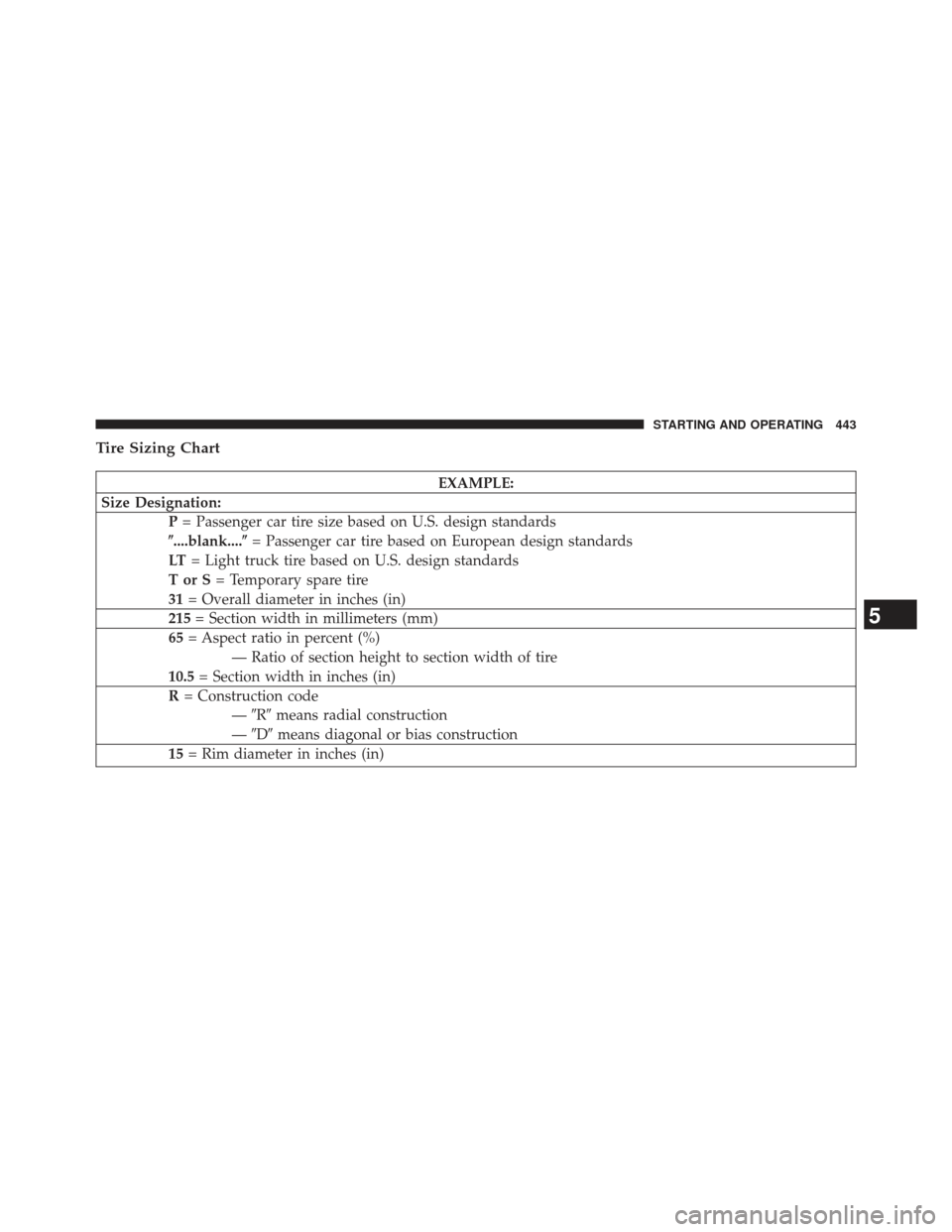
Tire Sizing Chart
EXAMPLE:
Size Designation: P= Passenger car tire size based on U.S. design standards
�....blank....� = Passenger car tire based on European design standards
LT = Light truck tire based on U.S. design standards
TorS= Temporary spare tire
31 = Overall diameter in inches (in)
215 = Section width in millimeters (mm)
65 = Aspect ratio in percent (%)
— Ratio of section height to section width of tire
10.5 = Section width in inches (in)
R = Construction code
—�R� means radial construction
— �D� means diagonal or bias construction
15 = Rim diameter in inches (in)
5
STARTING AND OPERATING 443
Page 451 of 631
 tire size designed for your vehicle
4) cold tire inflation pressures for the front, rear, and
spare tires.
Loading
The vehicle maximum load on the tire must not exceed
the load carrying capacity of")
3) tire size designed for your vehicle
4) cold tire inflation pressures for the front, rear, and
spare tires.
Loading
The vehicle maximum load on the tire must not exceed
the load carrying capacity of the tire on your vehicle. You
will not exceed the tire’s load carrying capacity if you
adhere to the loading conditions, tire size, and cold tire
inflation pressures specified on the Tire and Loading
Information placard and in the “Vehicle Loading” section
of this manual.
NOTE:Under a maximum loaded vehicle condition,
gross axle weight ratings (GAWRs) for the front and rear
axles must not be exceeded. For further information on
GAWRs, vehicle loading, and trailer towing, refer to
“Vehicle Loading” in this section. To determine the maximum loading conditions of your
vehicle, locate the statement “The combined weight of
occupants and cargo should never exceed XXX lbs or
XXX kg” on the Tire and Loading Information placard.
The combined weight of occupants, cargo/luggage and
trailer tongue weight (if applicable) should never exceed
the weight referenced here.
Steps For Determining Correct Load Limit
1. Locate the statement “The combined weight of occu-
pants and cargo should never exceed XXX lbs or
XXX kg” on your vehicle’s placard.
2. Determine the combined weight of the driver and passengers that will be riding in your vehicle.
3. Subtract the combined weight of the driver and pas- sengers from XXX lbs or XXX kg.
5
STARTING AND OPERATING 449