Page 213 of 520

charging system is experiencing a problem. See your
local authorized dealer to obtain service immediately.
If jump starting is required, refer to “Jump Starting
Procedures” in “What To Do In Emergencies”.
7. Electronic Throttle Control (ETC) Warning LightThis light will turn on briefly as a bulb check
when the ignition switch is placed in ON/
RUN. This light will also turn on while the
engine is running if there is a problem with the Electronic
Throttle Control (ETC) system.
If the light comes on while the engine is running, safely
bring the vehicle to a complete stop as soon as possible,
place the shift lever in PARK, for manual transmission
place the transmission in neutral, apply the parking
brake, and cycle the ignition key. The light should turn
off. If the light remains lit with the engine running, your
vehicle will usually be drivable. However, see an autho-
rized dealer for service as soon as possible. If the light is flashing when the engine is running,
immediate service is required. In this case, you may
experience reduced performance, an elevated/rough idle
or engine stall, and your vehicle may require towing.
Also, have the system checked by an authorized dealer if
the light does not come on during starting.
8. Temperature Gauge
The temperature gauge shows engine coolant tempera-
ture. Any reading within the normal range indicates that
the engine cooling system is operating satisfactorily.
The gauge pointer will likely indicate a higher tempera-
ture when driving in hot weather, up mountain grades,
or when towing a trailer. It should not be allowed to
exceed the upper limits of the normal operating range.
4
UNDERSTANDING YOUR INSTRUMENT PANEL 211
Page 222 of 520

23. Anti-Lock Brake (ABS) LightThis light monitors the Anti-Lock Brake System
(ABS). The light will turn on when the ignition
switch is placed in the ON/RUN position and
may stay on for as long as four seconds.
If the ABS light remains on or turns on while driving, it
indicates that the Anti-Lock portion of the brake system
is not functioning and that service is required. However,
the conventional brake system will continue to operate
normally if the BRAKE warning light is not on.
If the ABS light is on, the brake system should be serviced
as soon as possible to restore the benefits of Anti-Lock
brakes. If the ABS light does not turn on when the
ignition switch is placed in the ON/RUN position, have
the light inspected by an authorized dealer. 24. Low Fuel Light
This light will turn on and a single chime will
sound when the fuel level drops to 1/8 tank.
25. Malfunction Indicator Light (MIL)
The Malfunction Indicator Light (MIL) is part of an
onboard diagnostic system called OBD. The OBD
system monitors engine and automatic transmission
control systems. The MIL will turn on when the ignition is in
the ON/RUN position before engine start. If the MIL does
not come on when turning the key from OFF to ON/RUN,
have the condition checked promptly.
Certain conditions, such as a loose or missing gas cap,
poor fuel quality, etc., may illuminate the MIL after
engine start. The vehicle should be serviced if the MIL
stays on through several of your typical driving cycles. In
most situations, the vehicle will drive normally and will
not require towing.
220 UNDERSTANDING YOUR INSTRUMENT PANEL
Page 284 of 520

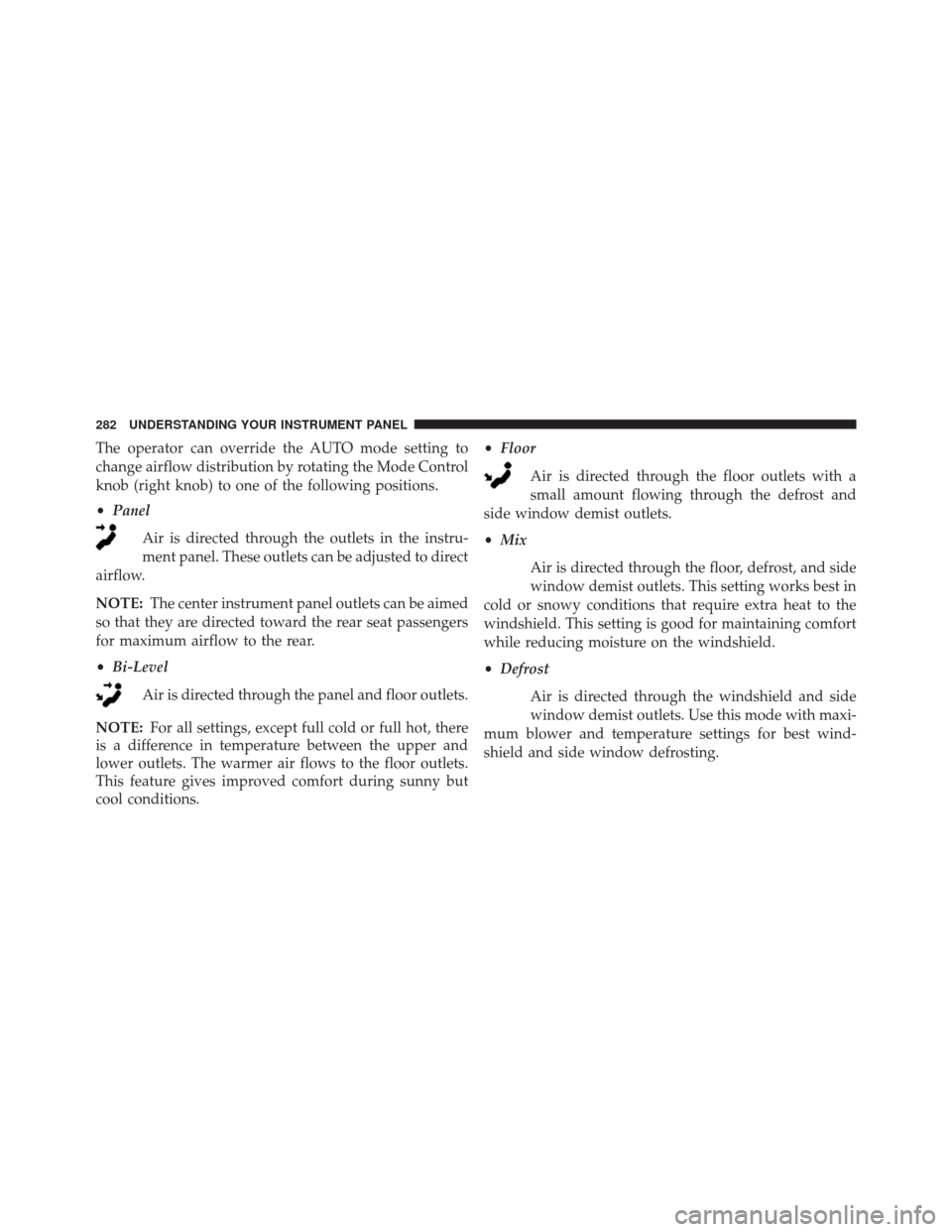
The operator can override the AUTO mode setting to
change airflow distribution by rotating the Mode Control
knob (right knob) to one of the following positions.
•Panel
Air is directed through the outlets in the instru-
ment panel. These outlets can be adjusted to direct
airflow.
NOTE: The center instrument panel outlets can be aimed
so that they are directed toward the rear seat passengers
for maximum airflow to the rear.
• Bi-Level
Air is directed through the panel and floor outlets.
NOTE: For all settings, except full cold or full hot, there
is a difference in temperature between the upper and
lower outlets. The warmer air flows to the floor outlets.
This feature gives improved comfort during sunny but
cool conditions. •
Floor
Air is directed through the floor outlets with a
small amount flowing through the defrost and
side window demist outlets.
• Mix
Air is directed through the floor, defrost, and side
window demist outlets. This setting works best in
cold or snowy conditions that require extra heat to the
windshield. This setting is good for maintaining comfort
while reducing moisture on the windshield.
• Defrost
Air is directed through the windshield and side
window demist outlets. Use this mode with maxi-
mum blower and temperature settings for best wind-
shield and side window defrosting.
282 UNDERSTANDING YOUR INSTRUMENT PANEL
Page 287 of 520

Side Window Demisters
A side window demister outlet is located at each end of
the instrument panel. These non-adjustable outlets direct
air toward the side windows when the system is in the
FLOOR, MIX, or DEFROST mode. The air is directed at
the area of the windows through which you view the
outside mirrors.
Outside Air Intake
Make sure the air intake, located directly in front of the
windshield, is free of obstructions such as leaves. Leaves
collected in the air intake may reduce airflow, and if they
enter the plenum, they could plug the water drains. In
winter months, make sure the air intake is clear of ice,
slush, and snow.
A/C Air Filter
The A/C Filter prevents most dust and pollen from
entering the cabin. The filter acts on air coming from
outside the vehicle and recirculated air within the pas-
senger compartment. Refer to “Maintenance Procedures”
in “Maintaining Your Vehicle” for A/C Air Filter service
information or see your authorized dealer for service.
Refer to “Maintenance Schedules” for filter service inter-
vals.
4
UNDERSTANDING YOUR INSTRUMENT PANEL 285
Page 292 of 520
▫Gasoline/Oxygenate Blends ..............376
▫ E-85 Usage In Non-Flex Fuel Vehicles .......376
▫ MMT In Gasoline .....................377
▫ Materials Added To Fuel ................377
▫ Fuel System Cautions ...................378
▫ Carbon Monoxide Warnings .............379
� ADDING FUEL ....................... .379
▫ Fuel Filler Cap (Gas Cap) ...............379
▫ Loose Fuel Filler Cap Message ............381
� VEHICLE LOADING ....................382 ▫
Vehicle Certification Label ...............382
▫ Gross Vehicle Weight Rating (GVWR) .......383
▫ Gross Axle Weight Rating (GAWR) .........383
▫ Overloading ........................ .384
▫ Loading ........................... .384
� TRAILER TOWING .....................384
� RECREATIONAL TOWING (BEHIND
MOTORHOME, ETC.) ...................385
▫ Towing This Vehicle Behind Another Vehicle . .385
290 STARTING AND OPERATING
Page 294 of 520

Normal Starting With Integrated Key – Manual
Transmission
Normal starting of either a cold or a warm engine does
not require pumping or pressing the accelerator pedal.
Press the clutch pedal fully to the floor, and turn the
ignition switch to the START position and release when
the engine starts. If the engine fails to start within 15
seconds, turn the ignition switch to the OFF position,
wait 10 to 15 seconds, then repeat the “Normal Starting”
procedure.
WARNING!
Do not attempt to push or tow your vehicle to get it
started. Unburned fuel could enter the catalytic con-
verter and once the engine has started, ignite and
damage the converter and vehicle. If the vehicle has
a discharged battery, booster cables may be used to
(Continued)
WARNING!(Continued)
obtain a start from another vehicle. This type of start
can be dangerous if done improperly, so follow the
procedure carefully. Refer to “Jump Starting” in
“What To Do In Emergencies” for further informa-
tion.
Automatic Transmission – If Equipped
The shift lever must be in the NEUTRAL or PARK
position before you can start the engine. Apply the brakes
before shifting into any driving gear.
CAUTION!
Damage to the transmission may occur if the follow-
ing precautions are not observed:
(Continued)
292 STARTING AND OPERATING
Page 300 of 520

WARNING!(Continued)
•Do not attempt to push or tow your vehicle to get it
started. Vehicles equipped with an automatic trans-
mission cannot be started this way. Unburned fuel
could enter the catalytic converter and once the
engine has started, ignite and damage the converter
and vehicle.
• If the vehicle has a discharged battery, booster
cables may be used to obtain a start from a booster
battery or the battery in another vehicle. This type
of start can be dangerous if done improperly. Refer
to “Jump Starting” in “What To Do In Emergen-
cies” for further information.
Clearing A Flooded Engine (Using ENGINE
START/STOP Button) – Automatic Transmission
Only
If the engine fails to start after you have followed the
“Normal Starting” or “Extreme Cold Weather� proce-
dures, it may be flooded. To clear any excess fuel, press
and hold the brake pedal, push the accelerator pedal all
the way to the floor and hold it, then press and release the
ENGINE START/STOP button once. The starter motor
will engage automatically, run for 10 seconds, and then
disengage. Once this occurs, release the accelerator pedal
and the brake pedal, wait 10 to 15 seconds, then repeat
the “Normal Starting” procedure.
298 STARTING AND OPERATING
Page 304 of 520

Shifting
Fully press the clutch pedal and lift your foot off the
accelerator pedal before shifting gears. As you release the
clutch pedal, lightly press the accelerator pedal. Damage
to the transmission or clutch may occur if you do not
fully press the clutch pedal and lift off of the accelerator
pedal when shifting.
The six-speed manual transmission has a spring that
centers the shift lever near third and fourth gear. This
spring helps you know which gear you are in when you
are shifting. Be careful when shifting from first to second
or downshifting from sixth to fifth.
The spring will try to pull the shift lever toward third and
fourth gear. Make sure you move the shift lever into
second or fifth gear. If you let the shift lever move in the
direction of the pulling, you may end shifting from first
to fourth or from sixth to third gear.
CAUTION!
Always make sure the vehicle comes to a complete
stop before shifting into REVERSE. Failure to do so
may result in transmission damage.
You must always use first gear (or Reverse) when starting
from a standing position.
Recommended Shift Speeds
To utilize your manual transmission efficiently for fuel
economy, it should be upshifted as listed in recom-
mended shift speed chart.
MANUAL TRANSMISSION
RECOMMENDED SHIFT SPEEDS 1-4 4-5 5-6
mph 20 3748
(km/h) (32) (59) (77)
302 STARTING AND OPERATING