2013 DODGE AVENGER mount
[x] Cancel search: mountPage 418 of 519
8. Disconnect the opposite end of the positive(+)jumper
cable from the positive (+)post of the booster battery.
9. Disconnect the positive (+)end of the jumper cable
from the remote positive (+)post of the discharged
vehicle.
10. Reinstall the protective cover over the remote posi- tive (+)battery post of the discharged vehicle.
If frequent jump-starting is required to start your vehicle,
you should have the battery and charging system in-
spected at your authorized dealer.
CAUTION!
Accessories plugged into the vehicle power outlets
draw power from the vehicle’s battery, even when not
in use (i.e., cellular phones, etc.). Eventually, if
(Continued)
CAUTION! (Continued)
plugged in long enough without engine operation,
the vehicle’s battery will discharge sufficiently to
degrade battery life and/or prevent the engine from
starting.
FREEING A STUCK VEHICLE
If your vehicle becomes stuck in mud, sand, or snow, it
can often be moved using a rocking motion. Turn the
steering wheel right and left to clear the area around the
front wheels. Then shift back and forth between DRIVE
and REVERSE, while gently pressing the accelerator. Use
the least amount of accelerator pedal pressure that will
maintain the rocking motion, without spinning the
wheels, or racing the engine.
416 WHAT TO DO IN EMERGENCIES
Page 438 of 519
WARNING!
•Battery fluid is a corrosive acid solution and can
burn or even blind you. Do not allow battery fluid
to contact your eyes, skin, or clothing. Do not lean
over a battery when attaching clamps. If acid
splashes in eyes or on skin, flush the area imme-
diately with large amounts of water.
• Battery gas is flammable and explosive. Keep
flame or sparks away from the battery. Do not use
a booster battery or any other booster source with
an output greater than 12 Volts. Do not allow cable
clamps to touch each other.
• Battery posts, terminals, and related accessories
contain lead and lead compounds. Wash hands
after handling.
CAUTION!
• It is essential when replacing the cables on the
battery that the positive cable is attached to the
positive post and the negative cable is attached to
the negative post. Battery posts are marked posi-
tive (+) and negative (-) and are identified on the
battery case. Cable clamps should be tight on the
terminal posts and free of corrosion.
• If a “fast charger” is used while the battery is in the
vehicle, disconnect both vehicle battery cables be-
fore connecting the charger to the battery. Do not
use a “fast charger” to provide starting voltage.
436 MAINTAINING YOUR VEHICLE
Page 442 of 519

7. Install the A/C Air Filter with the arrow on the filterpointing toward the floor. When installing the filter
cover, make sure the retaining tabs fully engage the
cover.
CAUTION!
The A/C air filter is identified with an arrow to
indicate airflow direction through the filter. Failure
to install the filter properly will result in the need to
replace it more often.
8. Reinstall the glove box door dampener and glove box.
Body Lubrication
Locks and all body pivot points, including such items as
seat tracks, door hinge pivot points and rollers, liftgate,
tailgate, sliding doors and hood hinges, should be lubri-
cated periodically with a lithium based grease, such as MOPAR® Spray White Lube to assure quiet, easy opera-
tion and to protect against rust and wear. Prior to the
application of any lubricant, the parts concerned should
be wiped clean to remove dust and grit; after lubricating
excess oil and grease should be removed. Particular
attention should also be given to hood latching compo-
nents to ensure proper function. When performing other
underhood services, the hood latch, release mechanism
and safety catch should be cleaned and lubricated.
The external lock cylinders should be lubricated twice a
year, preferably in the Fall and Spring. Apply a small
amount of a high quality lubricant, such as MOPAR®
Lock Cylinder Lubricant directly into the lock cylinder.Windshield Wiper Blades
Clean the rubber edges of the wiper blades and the
windshield periodically with a sponge or soft cloth and a
mild nonabrasive cleaner. This will remove accumula-
tions of salt or road film.
440 MAINTAINING YOUR VEHICLE
Page 449 of 519
Please review these recommendations for using Organic
Additive Technology (OAT) engine coolant (antifreeze)
that meets the requirements of Chrysler Material Stan-
dard MS-12106. When adding engine coolant (antifreeze):
•We recommend using MOPAR® Antifreeze/Coolant
10 Year/150,000 Mile Formula OAT (Organic Additive
Technology) that meets the requirements of Chrysler
Material Standard MS-12106.
• Mix a minimum solution of 50% OAT engine coolant
that meets the requirements of Chrysler Material Stan-
dard MS-12106 and distilled water. Use higher concen-
trations (not to exceed 70%) if temperatures below
�34° F (�37° C) are anticipated.
• Use only high purity water such as distilled or deion-
ized water when mixing the water/engine coolant
(antifreeze) solution. The use of lower quality water
will reduce the amount of corrosion protection in the
engine cooling system. Please note that it is the owner’s responsibility to main-
tain the proper level of protection against freezing ac-
cording to the temperatures occurring in the area where
the vehicle is operated.
NOTE:
Mixing engine coolant (antifreeze) types is not
recommended and can result in cooling system damage.
If HOAT and OAT coolant are mixed in an emergency,
have a authorized dealer drain, flush, and refill with OAT
coolant (conforming to MS-12106) as soon as possible.
Cooling System Pressure Cap
The cap must be fully tightened to prevent loss of engine
coolant (antifreeze), and to ensure that engine coolant
(antifreeze) will return to the radiator from the coolant
recovery tank.
The cap should be inspected and cleaned if there is any
accumulation of foreign material on the sealing surfaces.
7
MAINTAINING YOUR VEHICLE 447
Page 465 of 519
CavityCar-
tridge Fuse Mini
Fuse Description
1 40 Amp Green — Power Top Module
– If Equipped
Cavity Car-
tridge Fuse Mini
Fuse Description
2 — 20 Amp YellowBrake Vacuum
Pump
3 — 10 Amp RedCenter High
Mounted Stop Light
(CHMSL)/Brake
Switch
4 — 10 Amp RedIgnition Switch
5 — 20 Amp YellowTrailer Tow –
If Equipped
6 — 10 Amp RedPower Mirror
Switch/Climate
Controls
Integrated Power Module
7
MAINTAINING YOUR VEHICLE 463
Page 471 of 519

Bulb Number
Shift Indicator Lamp A6220
Rear Compartment
(Trunk) Lamp IKLE14140
NOTE: For lighted switches, see your authorized
dealer for replacement.
Exterior Bulbs
Bulb Number
Low Beam Headlamp 9006
High Beam Headlamp 9005
Front Park/Turn Signal
Lamp 3457A
Front Fog Lamp H11
Front Side Marker Lamp WY5W
Bulb Number
Center High Mounted
Stop (CHMSL) Lamp LED (Serviced at
Authorized Dealer)
Rear Tail/Stop/Turn
Signal Lamp LED (Serviced at
Authorized Dealer)
Backup Lamp 921
License Lamp W5W
BULB REPLACEMENT
NOTE:Lens fogging can occur under certain atmo-
spheric conditions. This will usually clear as atmospheric
conditions change to allow the condensation to change
back into a vapor. Turning the lamps on will usually
accelerate the clearing process.
7
MAINTAINING YOUR VEHICLE 469
Page 514 of 519
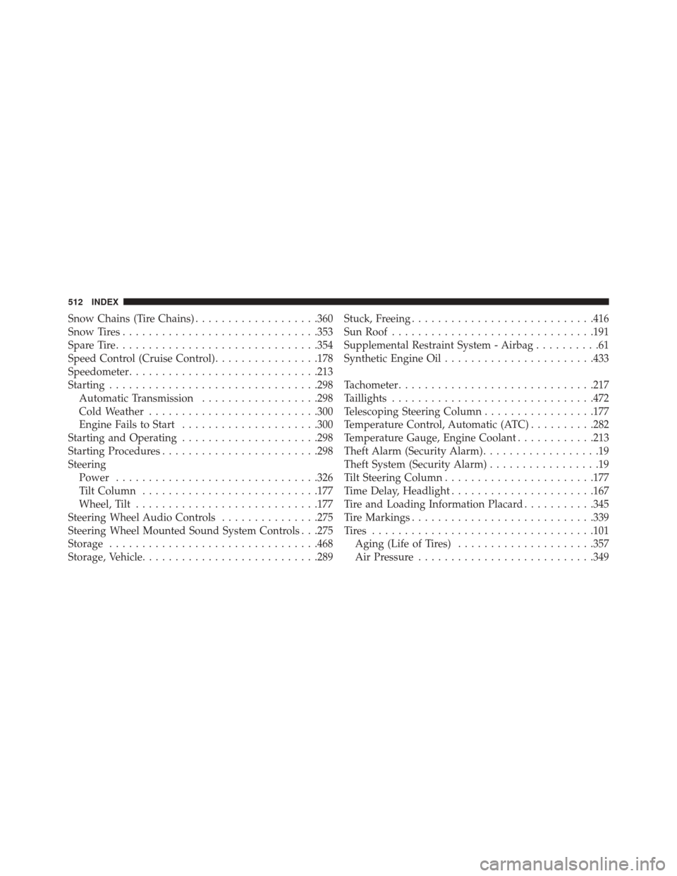
Snow Chains (Tire Chains)...................360
Snow Tires ............................. .353
Spare Tire .............................. .354
Speed Control (Cruise Control) ................178
Speedometer ............................ .213
Starting ............................... .298
Automatic Transmission ..................298
Cold Weather ......................... .300
Engine Fails to Start .....................300
Starting and Operating .....................298
Starting Procedures ....................... .298
Steering Power .............................. .326
Tilt Column .......................... .177
Wheel, Tilt ........................... .177
Steering Wheel Audio Controls ...............275
Steering Wheel Mounted Sound System Controls . . .275
Storage ............................... .468
Storage, Vehicle .......................... .289Stuck, Freeing
........................... .416
Sun Roof .............................. .191
Supplemental Restraint System - Airbag ..........61
Synthetic Engine Oil ...................... .433
Tachometer ............................. .217
Taillights .............................. .472
Telescoping Steering Column .................177
Temperature Control, Automatic (ATC) ..........282
Temperature Gauge, Engine Coolant ............213
Theft Alarm (Security Alarm) ..................19
Theft System (Security Alarm) .................19
Tilt Steering Column ...................... .177
Time Delay, Headlight ..................... .167
Tire and Loading Information Placard ...........345
Tire Markings ........................... .339
Tires ................................. .101
Aging (Life of Tires) .....................357
Air Pressure .......................... .349
512 INDEX
Page 518 of 519

INSTALLATION OF RADIO TRANSMITTING EQUIPMENT
Special design considerations are incorporated into this vehi-
cle’s electronic system to provide immunity to radio frequency
signals. Mobile two-way radios and telephone equipment must
be installed properly by trained personnel. The following must
be observed during installation.
The positive power connection should be made directly to the
battery and fused as close to the battery as possible. The
negative power connection should be made to body sheet metal
adjacent to the negative battery connection. This connection
should not be fused.
Antennas for two-way radios should be mounted on the roof or
the rear area of the vehicle. Care should be used in mounting
antennas with magnet bases. Magnets may affect the accuracy
or operation of the compass on vehicles so equipped.The antenna cable should be as short as practical and routed
away from the vehicle wiring when possible. Use only fully
shielded coaxial cable.
Carefully match the antenna and cable to the radio to ensure a
low Standing Wave Ratio (SWR).
Mobile radio equipment with output power greater than normal
may require special precautions.
All installations should be checked for possible interference
between the communications equipment and the vehicle’s
electronic systems.