2013 Citroen C4 PICASSO service indicator
[x] Cancel search: service indicatorPage 29 of 420

1
27
Monitoring
State of indicator lamps
Some buttons contain an indicator lamp that
gives the state of the corresponding function.
Green indicator: you have switched on the corresponding function.
Orange indicator: you have switched off thecorresponding function.
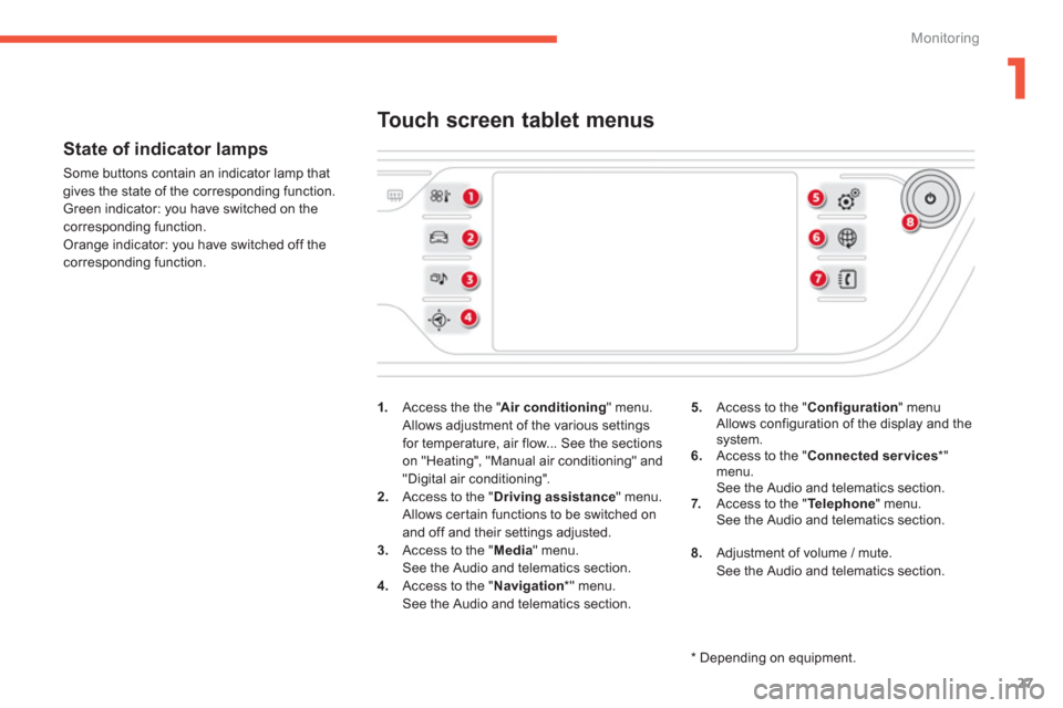
1
.Access the the "Air conditioning" menu.
Allows adjustment of the various settings for temperature, air flow... See the sections
on "Heating", "Manual air conditioning" and"Digital air conditioning".
2. Access to the "Driving assistance" menu.
Allows certain functions to be switched on
and off and their settings adjusted. 3. Access to the "Media
" menu.See the Audio and telematics section.4.
Access to the "Navigation*
" menu.See the Audio and telematics section.
Touch screen tablet menus
5.Access to the "Configuration
" menu Allows configuration of the display and thesystem.
6. Access to the "Connected services*"menu.
See the Audio and telematics section. 7.Access to the " Telephone " menu.
See the Audio and telematics section.
8.
Adjustment of volume / mute.
See the Audio and telematics section.
*
Depending on equipment.
Page 35 of 420

1
33
Monitoring
Type 1 instrument panel
Rev counter (x 1 000 rpm or tr/min),graduation according to engine (petrol or
Diesel).2.Gear shift indicator, selector position and gear for an electronic or automaticgearbox. 3.Digital speedometer (mph or km/h).4. Cruise control or speed limiter settings.
Dials and screens
5.
Fuel gauge. 6.
Ser vice indicator, then total mileagerecorder (miles or km).
These functions are displayed in turn when
the ignition is switched on. 7. Tr i p m i l e age recorder (miles or km).8.
Repeat of air conditioning information.
A.Main lighting dimmer buttons. B.
Recall servicing information.
Reset the function selected to zero (service
indicator or trip recorder).
Control buttons
Page 36 of 420

34
Monitoring
This instrument panel is presented in the form of a 12-inch panoramic HD screen.
It can be personalised. Depending on the display mode selected, some information can be hidden (see "Personalisation of the instrument panel").
Type 2 instrument panel
1.
Rev counter (x 1000 tr/min or rpm) ("DIALS" mode).2.
Gear shift indicator, position of the selector lever and the gear on an electronic or automatic gearbox.3.Digital speedometer (mph or km/h).4.
Cruise control or speed limiter setting. A
.Recall servicing information.
Reset the function selected to zero (service
indicator or trip recorder).
Control button Dials and screens
5.Fuel gauge.
6. Total distance recorder (miles or km).
7.Trip distance recorder (miles or km).8. Repeat of the air conditioning settings. 9.Repeat of the current media or telephone
information.
10. Repeat of the navigation information.
Page 52 of 420

50
Monitoring
Under-inflationfixed.The pressure in one or more wheelsis too low. Check the pressure of the tyres as soon as possible.
This check should preferably be carried out when the
tyres are cold.
You must reinitialise the system after the adjustment
of one or more tyre pressures and after changing one or more wheels.
+
flashing then fixed, accompanied by the Service warning lamp.The s
ystem has fault: the tyrepressures are no longer monitored.Check the tyre pressures as soon as possible.
Have the system checked by a CITROËN dealer or a
qualified workshop.
Warning / indicator lampStateCauseAction / Observations
Foot on thebrake pedal*fixed. The brake pedal is not pressed. With an electronic gearbox, press the brake pedal to start the engine (lever in position N ).
If you wish to release the parking brake withoutpressing the brake pedal, this warning lamp will
remain on.
With an automatic gearbox, press the brake pedal to move the gear selector out of position P.P
flashing. With an electronic gearbox, if you hold the vehicle on an incline using
the accelerator for too long, the clutch overheats. Use the brake pedal and/or the parkin
g brake.
Foot on theclutch*fixed. In the STOP mode of Stop & Start,changing to START mode is refused
because the clutch pedal is not fully down.You must declutch full
y to allow the change to engineSTA R T m o d e .
*
Only with the type 1 instrument panel
Page 53 of 420

1
51
Monitoring
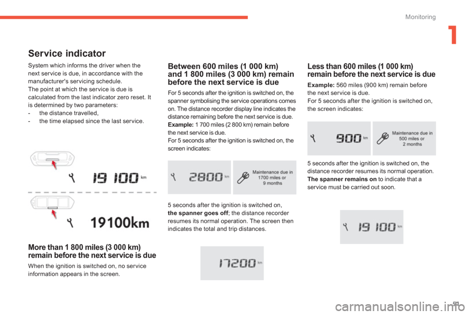
Service indicator
System which informs the driver when the next ser vice is due, in accordance with themanufacturer's servicing schedule.
The point at which the ser vice is due is
calculated from the last indicator zero reset. It
is determined by two parameters:
- the distance travelled,
- the time elapsed since the last service.
More than 1 800 miles (3 000 km)
remain before the next service is due
When the ignition is switched on, no ser vice
information appears in the screen.
Less than 600 miles (1 000 km)remain before the next service is due
Example:560 miles (900 km) remain before
the next service is due.
For 5 seconds after the ignition is switched on,
the screen indicates:
Between 600 miles (1 000 km)and 1 800 miles (3 000 km) remainbefore the next service is due
For 5 seconds after the ignition is switched on, the
spanner symbolising the ser vice operations comes
on. The distance recorder display line indicates the
distance remaining before the next ser vice is due.
Example:
1 700 miles (2 800 km) remain before
the next service is due.
For 5 seconds after the ignition is switched on, thescreen indicates:
5 seconds a
fter the ignition is switched on,the spanner goes off; the distance recorder fresumes its normal operation. The screen thenindicates the total and trip distances. 5 seconds a
fter the ignition is switched on, the distance recorder resumes its normal operation.
The spanner remains onto indicate that aservice must be carried out soon.
Page 54 of 420

52
Monitoring
Service overdue
For 5 seconds after the ignition is switched on,
the spanner flashesto indicate that the service must be carried out as soon as possible. Example:the ser vice is overdue by 186 miles (300 km).
For 5 seconds after the ignition is switched on,
the screen indicates:
The distance remaining may be weighted by the time factor, dependingon the driving conditions. Therefore, the spanner may also comeon if you have exceeded the period since the last service, indicated in the servicing and warranty booklet.
5 seconds after the ignition is switched on,
the distance recorder resumes its normal
operation. The spanner remains on.
Service indicator zero reset
After each ser vice, the ser vice indicator mustbe reset to zero.
The procedure for resetting to zero is as
follows: �) switch off the ignition,�)
press and hold the trip distance recorder
zero reset button,�) switch on the ignition; the distance recorder display begins a countdown, �)
when the display indicates "=0", release
the button; the spanner disappears.
Following this operation, if you wish to disconnect the battery, lock the vehicle and wait at least five minutes for the zero reset to be taken into account.
Retrieving the serviceinformation
You can access the ser vice information at anytime. �)Press the trip distance recorder zero reset button.
The ser vice information is displayed for afew seconds, then disappears.
Page 55 of 420

1
53
Monitoring
Engine oil level indicator
System which informs the driver whether theengine oil level is correct or not.
This information is indicated for a few secondswhen the ignition is switched on, after theservice information.
The level read will only be correct if the vehicle is on level ground and the engine has been off for more than30 minutes.
Oil level correct
This is indicated by a message in the instrument panel.
Oil level incorrect
This is indicated by a message in the instrument panel.
If the low oil level is confirmed by a check using
the dipstick, the level must be topped up to avoid damage to the engine.
Oil level indicator fault
This is indicated by a message in the
instrument panel. Contact a CITROËN dealer or a qualified workshop.
Dipstick
Refer to the "Checks" section to locate the
dipstick and the oil filler cap on your engine.
There are 2 marks on the dipstick:
-A
= max; never exceed this level,-B
= min; top up the level via
the oil filler, using the grade of oil suited to your engine.
Page 147 of 420

145
4
Driving
Emergency braking
In the event of a failure of the main servicebrake or in an exceptional situation (e.g. driver
taken ill, under instruction, etc
) a continuous
pull on the control lever will brake the vehicle.
Brakin
g takes place while the control lever is
being pulled. It is interrupted if the control lever
is released.
The ABS and DSC systems provide stability of
the vehicle during emergency braking.
If the emergency braking malfunctions, the
message "Parking brake control faulty" will be
displayed.
I
f a failure of the ABS and DSC systems, signalled by the illumination of one or both
warning lamps in the instrument panel, thenstability of the vehicle is no longer guaranteed.
In this event, stability must be assured by the
driver by repeating alternate "pull-release" actions on the control lever until the vehicle is immobilised.
The emergency braking should only be used in an exceptional situation.
Re
peat this procedure to reactivate automatic
operation.
Reactivation of automatic operation is
confirmed by the indicator lamp in the instrument panel going off.
Deactivating automatic
o
peration
In some situations, such as very cold weather
or towing (caravan, recovery), it may be necessary to deactivate automatic operation of
the system. �)Star t the engine.�)Apply the parking brake with the control
lever, if it is released. �)Ta k e your foot off the brake pedal.�)Push and hold the control lever in the release direction for at least 10 seconds and no more than 15 seconds.�)Release the control lever. �)Press and hold the brake pedal. �)Pull the control lever in the apply direction
for 2 seconds.
D
eactivation of the automatic functions
is confirmed by illumination of this
indicator lamp in the instrument panel.
�)Release the control lever and the brake pedal.
From this point the parkin
g brake can only
be applied and released manually using the control lever.