2013 CITROEN C4 DAG bulb
[x] Cancel search: bulbPage 5 of 340

CONTENTS
3
Direction indicators 139
Hazard warning lamps 139
Horn 139
Braking assistance systems 140
Trajectory control systems (ESP) 141
Emergency or assistance call 142
Front seat belts 143
Airbags 146
8 - SAFETY 139 149
Electric parking brake 150
Manual parking brake 157
Manual gearbox 157
Electronic gearbox 158
Automatic gearbox 161
Hill start assist 164
Gear effi ciency indicator 165
Tyre under-infl ation detection 166
Stop & Start 168
Lane departure warning system 171
Blind spot sensors 172
Speed limiter 176
Cruise control 178
Parking space sensors 180
Parking sensors 182
9 - DRIVING 150 183
Bonnet 185
Running out of fuel (Diesel) 186
Petrol engines 187
Diesel engines 188
Checking levels 189
Checks 191
10 - CHECKS 184 192
Temporary puncture repair kit 193
Changing a wheel 198
Snow chains 202
Changing a bulb 203
Changing a fuse 209
12 V battery 213
Energy economy mode 216
Changing a wiper blade 216
Fitting roof bars 217
Very cold climate screen 217
Towing the vehicle 218
Towing a trailer 220
Audio pre-equipment 221
Accessories 222
11 - PRACTICAL
INFORMATION 193 223
Petrol engines 224
Petrol weights 225
Diesel engines 226
Diesel weights 227
Dimensions 230
Identifi cation markings 231
12 - TECHNICAL
DATA 224 232
Emergency or assistance 233
eMyWay 235
Audio system 289
AUDIO and
TELEMATICS 233 322
ALPHABETICAL
INDEX 327 331 VISUAL SEARCH 323 326
Page 106 of 340

5
VISIBILITY
104
To avoid causing a nuisance to other
road users, the height of the halogen
headlamps should be adjusted accord-
ing to the load in the vehicle.
0.
1 or 2 people in the front seats.
-.
3 people.
1.
5 people.
-.
Intermediate setting.
2.
5 people + maximum authorised load.
-.
Intermediate setting.
3.
Driver + maximum authorised load.
MANUAL ADJUSTMENT OF
HALOGEN HEADLAMPS
The initial setting is position "0"
.
AUTOMATIC ADJUSTMENT OF
XENON HEADLAMPS
This system adjusts the height of the xe-
non headlamp beams automatically and
when stationary, according to the load in
the vehicle, so as to avoid causing a nui-
sance to other road user.
If a malfunction occurs, this
warning lamp is displayed
in the instrument panel, ac-
companied by an audible signal and a
message in the screen.
The system then places your headlam-
ps in the lowest position.
Do not touch the xenon bulbs.
Contact a CITROËN dealer or a
qualifi ed workshop.
Page 125 of 340

6
FITTINGS
123
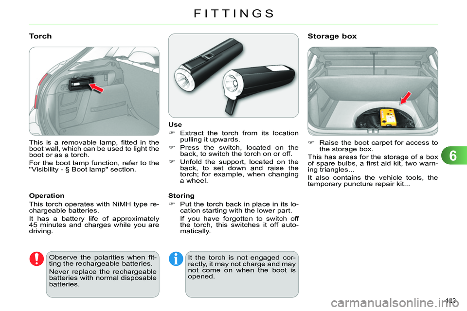
This is a removable lamp, fi tted in the
boot wall, which can be used to light the
boot or as a torch.
For the boot lamp function, refer to the
"Visibility - § Boot lamp" section.
Torch
Operation
This torch operates with NiMH type re-
chargeable batteries.
It has a battery life of approximately
45 minutes and charges while you are
driving.
Use
Extract the torch from its location
pulling it upwards.
Press the switch, located on the
back, to switch the torch on or off.
Unfold the support, located on the
back, to set down and raise the
torch; for example, when changing
a wheel.
Storing
Put the torch back in place in its lo-
cation starting with the lower part.
If you have forgotten to switch off
the torch, this switches it off auto-
matically.
Raise the boot carpet for access to
the storage box.
This has areas for the storage of a box
of spare bulbs, a fi rst aid kit, two warn-
ing triangles...
It also contains the vehicle tools, the
temporary puncture repair kit...
Storage box
Observe the polarities when fi t-
ting the rechargeable batteries.
Never replace the rechargeable
batteries with normal disposable
batteries. It the torch is not engaged cor-
rectly, it may not charge and may
not come on when the boot is
opened.
Page 205 of 340

11
PRACTICAL INFORMATION
203
CHANGING A BULB
The headlamps are fi tted with
polycarbonate glass with a pro-
tective coating:
do not clean them using a
dry or abrasive cloth, nor
with a detergent or solvent
product,
use a sponge and soapy wa-
ter or a pH neutral product,
when using a high pressure
washer on persistent marks,
do not keep the lance direct-
ed towards the lamps or their
edges for too long, so as not
to damage their protective
coating and seals.
Changing a bulb should only be
done after the headlamp has
been switched off for a few min-
utes (risk of serious burns).
Do not touch the bulb directly
with your fi ngers, use a lint-
free cloth.
It is imperative to use only anti-
ultraviolet (UV) type bulbs to
avoid damaging the headlamp.
Always replace a failed bulb with
a new bulb with the same type
and specifi cation.
Risk of electrocution
Xenon bulbs (D1S-35W) must
be replaced by a CITROËN
dealer or a qualifi ed workshop.
Front lamps
1.
Direction indicators (H21 clear).
2.
Dipped beam headlamps
(H7 - 55W).
3.
Main beam headlamps
(H1 - 55W).
4.
Daytime running lamps/
sidelamps (P21/5W XL).
5.
Foglamps (H11 - 55W).
1.
Directional dipped/main beam
headlamps (D1S-35W).
2.
Direction indicators
(PY21W amber).
3.
Daytime running lamps/
sidelamps (P21/5W XL).
4.
Foglamps (H11-55W).
Model with halogen headlamps
Model with xenon and directional
headlamps
Bulbs with lugs, type H1, H7...
take care to position them cor-
rectly to ensure the best lighting.
Page 206 of 340

11
PRACTICAL INFORMATION
204
Amber coloured bulbs, such as
the direction indicators, must be
replaced with bulbs of identical
specifi cations and colour.
When refi tting, close the protec-
tive cover carefully to preserve
the sealing of the headlamp.
Changing direction indicator bulbs
Model with halogen headlamps
Rapid fl ashing of the direction
indicator warning lamp (right
or left) indicates the failure of a
bulb on that side.
Access to bulbs
Remove the air defl ector by unclip-
ping each of its three attachment
points.
Unclip the bonnet release cable at
its two fi xings.
Move the cable down.
After changing the failed bulb, remember
to put everything back in place (cable and
air defl ector). Depending on the engine and only on
the left hand side, you must fi rst carry
out the following operations for access
to the protective covers on the bulbs.
Turn the bulb holder a quarter of a
turn and extract it.
Pull out the bulb and change it.
To reassemble, carry out these opera-
tions in reverse order.
Model with Xenon headlamps
Remove the protective cover by
pulling on its tongue.
Disconnect the electrical connector.
Separate the springs to release the
bulb.
Pull the bulb out and replace it.
To reassemble, carry out these opera-
tions in reverse order.
Page 207 of 340

11
PRACTICAL INFORMATION
205
Changing dipped beam headlamp
bulbs (only on models with halogen
headlamps)
Changing daytime running lamp/
sidelamp bulbs
Remove the protective cover by
pulling on the tab.
Disconnect the bulb connector.
Turn the bulb holder a quarter of a
turn and extract it.
Pull the bulb and change it.
To r efi t, carry out these operations in
reverse order.
Remove the protective cover by
pulling on the tab.
Disconnect the bulb connector.
Spread the springs to release the
bulb.
Extract the bulb and change it.
To reassemble, carry out these operations
in reverse order.
Changing main beam headlamp
bulbs (only on models with halogen
headlamps)
Remove the protective cover by
pulling on the tab.
Disconnect the bulb connector.
Squeeze the springs to release the
bulb.
Pull out the bulb and replace it.
To reassemble, carry out these operations
in reverse order.
Page 208 of 340

11
PRACTICAL INFORMATION
206
Introduce a fl at screwdriver in the
hole in the fi nisher.
Pull and lever to unclip the bumper
fi nisher (the parking sensor stays
with the fi nisher).
Remove the two module fi xing screws
and remove it from its housing.
Disconnect the bulb holder connector.
Turn the bulb holder a quarter of a
turn and extract it.
Pull the bulb and change it.
To r efi t, carry out these operations in
reverse order.
To replace these bulbs you may also
contact a CITROËN dealer or a qualifi ed
workshop.
Changing foglamp bulbs
Changing the side spotlamps
For the replacement of this type of LED
lamp, contact a CITROËN dealer or a
qualifi ed workshop.
Changing integrated direction
indicator side repeaters
Insert a screwdriver towards the
centre of the repeater between the
repeater and the base of the mirror.
Tilt the screwdriver to extract the re-
peater and remove it.
Disconnect the repeater connector.
To reassemble, carry out these operations
in reverse order.
Contact a CITROËN dealer or a qualifi ed
workshop to obtain replacement repeaters.
Page 209 of 340

11
PRACTICAL INFORMATION
207
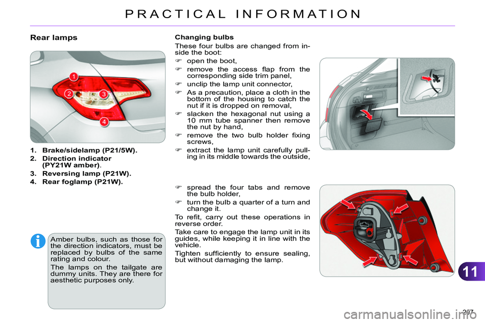
Rear lamps
1.
Brake/
sidelamp
(P21/5W).
2.
Direction
indicator
(PY21W amber)
.
3.
Reversing lamp (P21W).
4.
Rear
foglamp
(P21W).
Amber bulbs, such as those for
the direction indicators, must be
replaced by bulbs of the same
rating and colour.
The lamps on the tailgate are
dummy units. They are there for
aesthetic purposes only.
Changing bulbs
These four bulbs are changed from in-
side the boot:
open the boot,
remove the access fl ap from the
corresponding side trim panel,
unclip the lamp unit connector,
As a precaution, place a cloth in the
bottom of the housing to catch the
nut if it is dropped on removal,
slacken the hexagonal nut using a
10 mm tube spanner then remove
the nut by hand,
remove the two bulb holder fi xing
screws,
extract the lamp unit carefully pull-
ing in its middle towards the outside,
spread the four tabs and remove
the bulb holder,
turn the bulb a quarter of a turn and
change it.
To r efi t, carry out these operations in
reverse order.
Take care to engage the lamp unit in its
guides, while keeping it in line with the
vehicle.
Tighten suffi ciently to ensure sealing,
but without damaging the lamp.