Page 648 of 699
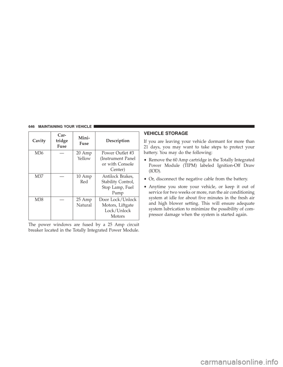
CavityCar-
tridge Fuse Mini-
Fuse Description
M36 — 20 Amp YellowPower Outlet #3
(Instrument Panel or with Console Center)
M37 — 10 Amp Red
Antilock Brakes,
Stability Control, Stop Lamp, Fuel Pump
M38 — 25 Amp NaturalDoor Lock/Unlock
Motors, LiftgateLock/Unlock Motors
The power windows are fused by a 25 Amp circuit
breaker located in the Totally Integrated Power Module.
VEHICLE STORAGE
If you are leaving your vehicle dormant for more than
21 days, you may want to take steps to protect your
battery. You may do the following:
• Remove the 60 Amp cartridge in the Totally Integrated
Power Module (TIPM) labeled Ignition-Off Draw
(IOD).
• Or, disconnect the negative cable from the battery.
• Anytime you store your vehicle, or keep it out of
service for two weeks or more, run the air conditioning
system at idle for about five minutes in the fresh air
and high blower setting. This will ensure adequate
system lubrication to minimize the possibility of com-
pressor damage when the system is started again.
646 MAINTAINING YOUR VEHICLE
Page 686 of 699
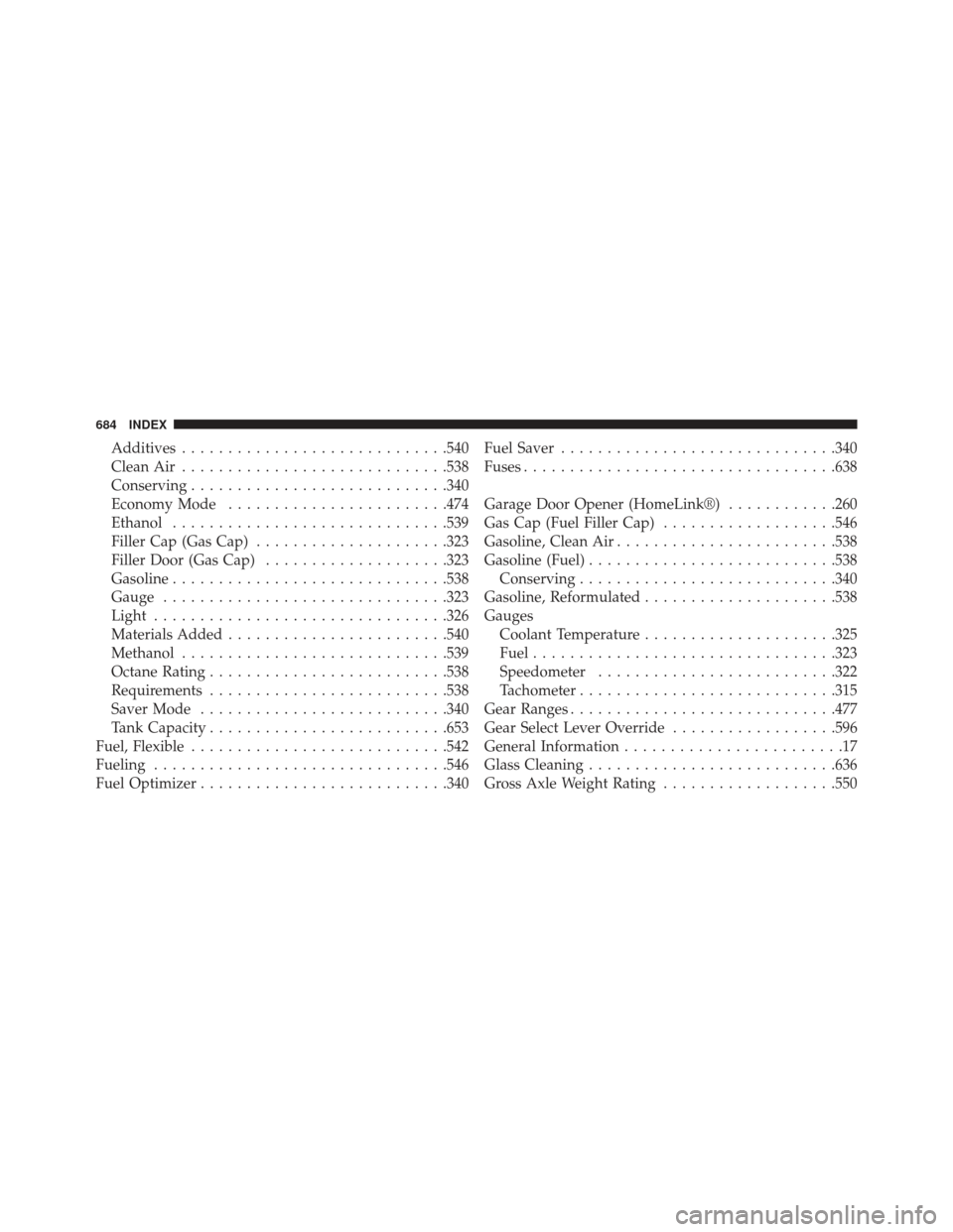
Additives............................ .540
Clean Air ............................ .538
Conserving ........................... .340
Economy Mode ....................... .474
Ethanol ............................. .539
Filler Cap (Gas Cap) .....................323
Filler Door (Gas Cap) ....................323
Gasoline ............................. .538
Gauge .............................. .323
Light ............................... .326
Materials Added ....................... .540
Methanol ............................ .539
Octane Rating ......................... .538
Requirements ......................... .538
Saver Mode .......................... .340
Tank Capacity ......................... .653
Fuel, Flexible ........................... .542
Fueling ............................... .546
Fuel Optimizer .......................... .340Fuel Saver
............................. .340
Fuses ................................. .638
Garage Door Opener (HomeLink®) ............260
Gas Cap (Fuel Filler Cap) ...................546
Gasoline, Clean Air ....................... .538
Gasoline (Fuel) .......................... .538
Conserving ........................... .340
Gasoline, Reformulated .....................538
Gauges Coolant Temperature .....................325
Fuel ................................ .323
Speedometer ......................... .322
Tachometer ........................... .315
Gear Ranges ............................ .477
Gear Select Lever Override ..................596
General Information ........................17
Glass
Cleaning .......................... .636
Gross Axle Weight Rating ...................550
684 INDEX
Page 688 of 699
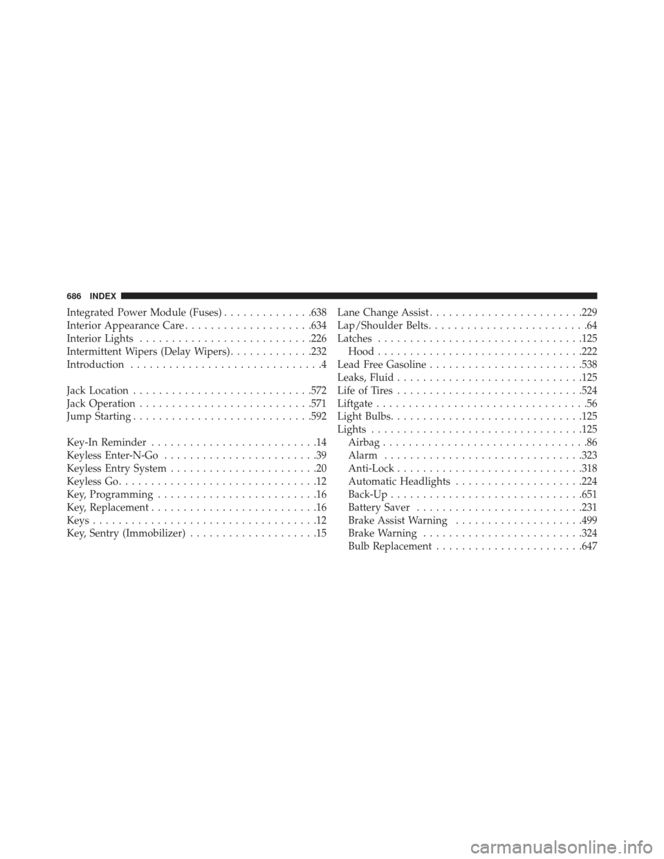
Integrated Power Module (Fuses)..............638
Interior Appearance Care ....................634
Interior Lights .......................... .226
Intermittent Wipers (Delay Wipers) .............232
Introduction ..............................4
Jack Location ........................... .572
Jack Operation .......................... .571
Jump Starting ........................... .592
Key-In Reminder ..........................14
Keyless Enter-N-Go ........................39
Keyless Entry System .......................20
Keyless Go ...............................12
Key, Programming .........................16
Key, Replacement ..........................16
Keys ...................................12
Key, Sentry (Immobilizer) ....................15 Lane Change Assist
....................... .229
Lap/Shoulder Belts .........................64
Latches ............................... .125
Hood ............................... .222
Lead Free Gasoline ....................... .538
Leaks, Fluid ............................ .125
Life of Tires ............................ .524
Liftgate .................................56
Light Bulbs ............................. .125
Lights ................................ .125
Airbag ................................86
Alarm .............................. .323
Anti-Lock ............................ .318
Automatic Headlights ....................224
Back-Up ............................. .651
Battery Saver ......................... .231
Brake Assist Warning ....................499
Brake Warning ........................ .324
Bulb Replacement ...................... .647
686 INDEX
Page 698 of 699
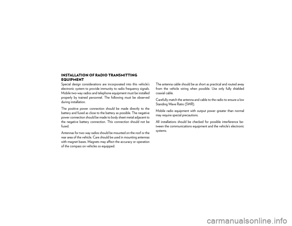
INSTALLATION OF RADIO TRANSMITTING
EQUIPMENTSpecial design considerations are incorporated into this vehicle’s
electronic system to provide immunity to radio frequency signals.
Mobile two-way radios and telephone equipment must be installed
properly by trained personnel. The following must be observed
during installation.
The positive power connection should be made directly to the
battery and fused as close to the battery as possible. The negative
power connection should be made to body sheet metal adjacent to
the negative battery connection. This connection should not be
fused.
Antennas for two-way radios should be mounted on the roof or the
rear area of the vehicle. Care should be used in mounting antennas
with magnet bases. Magnets may affect the accuracy or operation
of the compass on vehicles so equipped.The antenna cable should be as short as practical and routed away
from the vehicle wiring when possible. Use only fully shielded
coaxial cable.
Carefully match the antenna and cable to the radio to ensure a low
Standing Wave Ratio (SWR).
Mobile radio equipment with output power greater than normal
may require special precautions.
All installations should be checked for possible interference be-
tween the communications equipment and the vehicle’s electronic
systems.
Page:
< prev 1-8 9-16 17-24