2013 BMW X6M lights
[x] Cancel search: lightsPage 120 of 327

▷Approx. 7 ft/2 m to the side.▷Approx. 7 ft/2 m to the rear.
Obstacles up to the height of the exterior mir‐
rors are thus detected in a timely fashion.
System limits
Top View cannot be used in the following sit‐
uations:
▷With a door open.▷With the tailgate open.▷With an exterior mirror folded in.▷In poor light.
The arrows next to the vehicle are displayed in
a shaded form on the Control Display and a
symbol appears at the corresponding location
on the vehicle.
Check the traffic situation as well
Check the traffic situation around the ve‐
hicle with your own eyes. Otherwise, an acci‐
dent could result from road users or objects lo‐
cated outside the picture area of the
cameras.◀
Switching on automatically
Select transmission position R with the engine
running.
The images from Top View and PDC are dis‐
played when the system has been switched on
using iDrive.
Switching off automatically when
driving forward
The system switches off when a certain dis‐
tance or speed is exceeded.
Switch on the system again if necessary.
Switching on/off manually
Press the button.
▷On: the LED lights up.▷Off: the LED goes out.
If Top View is displayed, switch on the backup
camera via the iDrive, refer to page 115.
Visual warning
The approach to an object can be shown on
the Control Display.
When the distance to an object is small, the
PDC display correspondingly shows a red bar
in front of the vehicle.
The display appears as soon as Top View is
activated.
If the last image selected was the rearview
camera, this is displayed again. To switch to
Top View:
"Rear view camera" Select the symbol on
the Control Display.
The setting is stored for the remote control
currently in use.
Seite 116ControlsDriving comfort116
Online Edition for Part no. 01 40 2 910 876 - VII/13
Page 132 of 327
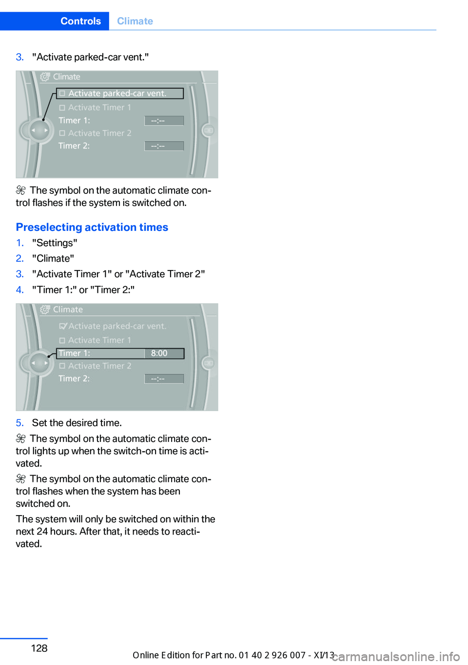
3."Activate parked-car vent."
The symbol on the automatic climate con‐
trol flashes if the system is switched on.
Preselecting activation times
1."Settings"2."Climate"3."Activate Timer 1" or "Activate Timer 2"4."Timer 1:" or "Timer 2:"5.Set the desired time.
The symbol on the automatic climate con‐
trol lights up when the switch-on time is acti‐
vated.
The symbol on the automatic climate con‐
trol flashes when the system has been
switched on.
The system will only be switched on within the
next 24 hours. After that, it needs to reacti‐
vated.
Seite 128ControlsClimate128
Online Edition for Part no. 01 40 2 910 876 - VII/13
Page 134 of 327

on the interior rearview mirror. The re‐
quired distance depends on the particular
hand-held transmitter.4.Press the button of the desired function on
the hand-held transmitter and the button
being programmed on the interior rearview
mirror simultaneously and hold. The LED
on the interior rearview mirror flashes
slowly at first.5.When the LED flashes more rapidly, re‐
lease both buttons. Rapid flashing indi‐
cates that the button on the interior rear‐
view mirror has been programmed.
If the LED does not flash faster after
60 seconds, change the distance between
the interior rearview mirror and the hand-
held transmitter and repeat the step. Multi‐
ple trials at different distances may be nec‐
essary. Wait at least 15 seconds between
trials.6.To program additional functions on other
buttons, repeat steps 3 to 5.
The systems can be operated with the buttons
on the interior rearview mirror.
Special characteristics of alternating-
code radio systems
If the system cannot be operated after re‐
peated programming, check whether the sys‐
tem to be operated uses an alternating-code
system.
Read the operating instructions of the system
or press and hold the programmed button on
the interior rearview mirror. If the LED on the
interior rearview mirror flashes rapidly at first
and then lights up continuously for 2 seconds,
the system is equipped with an alternating-
code system. This flashing LED pattern re‐
peats itself for approx. 20 seconds.
In systems with an alternating-code system,
the Universal Garage Door Opener and the
system must be additionally synchronized.
Please obtain additional information on syn‐
chronization in the operating instructions of
the system being set up.
The systems will be easier to synchronize with
the aid of a second person.
Synchronization:1.Park the vehicle within range of the re‐
mote-controlled system.2.Program the corresponding button on the
interior rearview mirror as described.3.Identify and press the synchronization but‐
ton on the system being set up. You have
approx. 30 seconds for the next step.4.Press and hold the button on the interior
rearview mirror for approx. 3 seconds and
then release it. Repeat this step up to three
times if necessary to complete the syn‐
chronization procedure. When synchroni‐
zation is completed, the programmed func‐
tion is executed.
Reprogramming individual buttons
1.Switch on the ignition.2.Hold the hand-held transmitter at a dis‐
tance of approx. 1 to 3 in/2.5 to 8 cm from
the memory buttons.
The required distance depends on the par‐
ticular hand-held transmitter.3.Press the memory button of the Universal
Garage Door Opener.4.If the LED flashes slowly after approx.
20 seconds, press the transmit button on
the hand-held transmitter.5.Release both buttons when the LED
flashes rapidly.
If the LED does not flash rapidly after ap‐
prox. 60 seconds, change the distance and
repeat the step.
Canada: if the LED does not flash rapidly
after approx. 60 seconds, change the dis‐
tance and repeat the step. If programmingSeite 130ControlsInterior equipment130
Online Edition for Part no. 01 40 2 910 876 - VII/13
Page 135 of 327

was aborted by the hand-held transmitter,
hold down the memory button and press
and release the button on the hand-held
transmitter several times for 2 seconds.
Controls
Prior to operation
Before operating a unit with the Universal
Garage Door Opener, ensure that there are no
people, animals, or objects in the range of
movement of the system; otherwise, there is a
risk of injury or damage.
Also follow the safety instructions of the hand-
held transmitter.◀
The system, such as the garage door, can be
operated using the button on the interior rear‐
view mirror with the engine running or the igni‐
tion switched on. When you are within the re‐
ception range of the system, press and hold
the button until the function is initiated. The
LED on the interior rearview mirror lights up
continuously while the radio signal is being
transmitted.
Deleting stored functions Press the right and left buttons on the interior
rearview mirror simultaneously for approx.
20 seconds until the LED flashes rapidly. All
stored functions are deleted. The functions
cannot be deleted individually.
Digital compass1Adjustment button2Display
The display shows you the main or secondary
compass direction in which you are driving.
Operating concept
Various functions can be called up by pressing
the adjustment button with a pointed object
such as a pen. The following adjustment op‐
tions are displayed one after the other, de‐
pending on how long the adjustment button is
pressed:
▷Press briefly: switch the display on/off.▷3 to 6 seconds: set the compass zone.▷6 to 9 seconds: calibrate the compass.▷9 to 12 seconds: set left-hand/right hand
steering.▷12 to 15 seconds: set the language.
Setting compass zones
Set the compass zone corresponding to the
vehicle's geographic location so that the com‐
pass can function correctly; refer to the world
map with compass zones.
Seite 131Interior equipmentControls131
Online Edition for Part no. 01 40 2 910 876 - VII/13
Page 158 of 327

Use coasting conditions
When approaching a red light, take your foot
off the accelerator and let the vehicle coast to
a halt.
On a downhill gradient, take your foot off the
accelerator and let the vehicle roll.
The flow of fuel is interrupted while coasting.
Switch off the engine during longer stops
Switch off the engine during longer stops, e.g.,
at traffic lights, railroad crossings or in traffic
congestion.
Fuel savings are already achieved after the en‐
gine is turned off for as little as 4 seconds.
Switch off any functions that
are not currently needed
Functions such as seat heating and the rear
window defroster require a lot of energy and
consume additional fuel, especially in city and
stop-and-go traffic.
Therefore, switch off these functions if they
are not actually needed.
Have maintenance carried
out
Have vehicles maintained regularly to achieve
optimal vehicle economy and operating life.
Have the maintenance carried out by your
service center.
Please also note the BMW Maintenance Sys‐
tem, refer to page 274.Seite 154Driving tipsSaving fuel154
Online Edition for Part no. 01 40 2 910 876 - VII/13
Page 279 of 327

Maintenance and repair should be performed
by your service center. Make sure to have reg‐
ular maintenance procedures recorded in the
vehicle's Service and Warranty Information
Booklet for US models, and in the Warranty
and Service Guide Booklet for Canadian mod‐
els. These entries are proof of regular mainte‐
nance.
Socket for OBD Onboard
Diagnosis
Socket for Onboard Diagnosis
The socket for Onboard Diagnosis may
only be used by the service center, by work‐
shops that operate according to the specifica‐
tions of the vehicle manufacturer with appro‐
priately trained personnel, and by other
authorized persons. Otherwise, its use may
lead to vehicle malfunctions.◀
On the driver's side is an OBD socket for
checking the primary components in the vehi‐
cle emissions.
Emissions
▷The warning lamp lights up:
Emissions are deteriorating. Have
the vehicle checked as soon as
possible.▷The warning lamp flashes under certain
circumstances:
This indicates that there is excessive mis‐
firing in the engine.Reduce the vehicle speed and have the
system checked immediately; otherwise,
serious engine misfiring within a brief pe‐
riod can seriously damage emission con‐
trol components, in particular the catalytic
converter.
Display of the previously described
malfunctions on Canadian models.
Fuel cap The indicator lamp lights up.
If the fuel cap is not properly tight‐
ened, the OBD system may conclude
that fuel vapor is escaping. If the cap is then
tightened, the display should go out in a short
time.
Seite 275MaintenanceMobility275
Online Edition for Part no. 01 40 2 910 876 - VII/13
Page 280 of 327

Replacing componentsVehicle equipmentThis chapter describes all series equipment as
well as country-specific and special equipment
offered for this model series.Therefore, it also
describes equipment that may not be found in
your vehicle, for instance due to the selected
special equipment or the country version. This
also applies to safety-related functions and
systems.
Tool kit
The tool kit is stowed under the cargo floor
panel in the cargo area.
Wiper blade replacement Do not fold down the wipers without
wiper blades
Do not fold down the wipers if wiper blades
have not been installed; this may damage the
windshield.◀
Front1.Fold up the wiper arm.2.Press the release button on the wiper arm,
see arrow 1.3.Pull off the wiper blade toward the front,
see arrow 2.
Lamp and bulb replacement
Notes
Lamps and bulbs
Lamps and bulbs make an essential contribu‐
tion to vehicle safety.
The manufacturer of the vehicle recommends
that you entrust corresponding procedures to
the service center if you are unfamiliar with them or they are not described here.
You can obtain a selection of replacement
bulbs at the service center.
Danger of burns
Only change bulbs when they are cool;
otherwise, there is the danger of getting
burned.◀
Working on the lighting system
When working on the lighting system,
you should always switch off the lights af‐
fected to prevent short circuits.
Seite 276MobilityReplacing components276
Online Edition for Part no. 01 40 2 910 876 - VII/13
Page 281 of 327

To avoid possible injury or equipment damage
when replacing bulbs, observe any instructions
provided by the bulb manufacturer.◀
Do not perform work/bulb replacement
on xenon headlamps
Have any work on the xenon lighting system,
including bulb replacement, performed only by
a service center.
Due to the high voltage present in the system,
there is the danger of fatal injuries if work is
carried out improperly.◀
Do not touch the bulbs
Do not touch the glass of new bulbs with
your bare hands, as even minute amounts of
contamination will burn into the bulb's surface
and reduce its service life.
Use a clean tissue, cloth or something similar,
or hold the bulb by its base.◀
Light-emitting diodes LED
Light-emitting diodes installed behind translu‐
cent lenses serve as the light source for many
of the controls, displays and other equipment
in your vehicle.
These light-emitting diodes, which operate us‐
ing a concept similar to that applied in conven‐
tional lasers, are officially designated as
Class 1 light-emitting diodes.
Do not remove the covers
Do not remove the covers, and never
stare into the unfiltered light for several hours; otherwise, irritation of the retina could result.◀
Headlamp glass
Condensation can form on the inside of the
headlamps in cool or humid weather. When
you drive with the lights switched on, the con‐
densation evaporates after a short time. The
headlamps do not need to be changed.
If the condensation in the headlamps does not
evaporate after trips with the lights switchedon, and the amount of moisture in the head‐
lamps increases, for example if water droplets
form, have them checked by your service cen‐
ter.
Changing the lamps
Xenon headlamps
Notes
Because of the long life of these bulbs, the
likelihood of failure is very low. Switching the
lamps on and off frequently shortens their life.
If a xenon bulb fails, switch on the front fog
lamps and continue the trip with great care.
Comply with local regulations.
Do not perform work/bulb replacement
on xenon headlamps
Have any work on the xenon lighting system,
including bulb replacement, performed only by
a service center.
Due to the high voltage present in the system,
there is the danger of fatal injuries if work is
carried out improperly.◀
Follow the general instructions on lamps and
bulbs, refer to page 276.
Parking lamps, roadside parking
lamps, daytime running lights
The illustration shows the left side of the en‐
gine compartment.Seite 277Replacing componentsMobility277
Online Edition for Part no. 01 40 2 910 876 - VII/13