2013 BMW X6M display
[x] Cancel search: displayPage 278 of 327

MaintenanceVehicle equipment
This chapter describes all series equipment as
well as country-specific and special equipment
offered for this model series.Therefore, it also
describes equipment that may not be found in
your vehicle, for instance due to the selected
special equipment or the country version. This
also applies to safety-related functions and
systems.
BMW Maintenance System
The maintenance system provides information
on required maintenance measures and thus
provides support in maintaining road safety
and the operational reliability of the vehicle.
Condition Based Service
CBS
Sensors and special algorithms take into ac‐
count the driving conditions of your vehicle.
Based on this, Condition Based Service deter‐
mines the maintenance requirements.
The system makes it possible to adapt the
amount of maintenance you need to your user
profile.
Details on the service requirements, refer to
page 74, can be displayed on the Control Dis‐
play.
On the Control Display, the remaining distan‐
ces and times for selected maintenance re‐
quirements and any legally required deadlines
can be displayed individually, refer to page 74.
Service data in the remote control Information on the required maintenance is
continuously stored in the remote control. Your service center will read out this data and
suggest the right array of service procedures
for your vehicle.
Therefore, hand your service specialist the re‐
mote control that you used most recently.
Setting the correct date
Make sure the date is set correctly, refer
to page 78; otherwise, the effectiveness of
CBS Condition Based Service is not ensured.◀
Storage periods Storage periods during which the vehicle bat‐
tery was disconnected are not taken into ac‐
count.
If this occurs, have a service center update the
time-dependent maintenance procedures,
such as checking brake fluid and, if necessary,
changing the engine oil and the microfilter/
activated-charcoal filter.
Service and Warranty
Information Booklet for US
models and Warranty and
Service Guide Booklet for Canadian models
Please consult your Service and Warranty In‐
formation Booklet for US models and Warranty
and Service Guide Booklet for Canadian mod‐
els for additional information on service re‐
quirements.Seite 274MobilityMaintenance274
Online Edition for Part no. 01 40 2 910 876 - VII/13
Page 279 of 327

Maintenance and repair should be performed
by your service center. Make sure to have reg‐
ular maintenance procedures recorded in the
vehicle's Service and Warranty Information
Booklet for US models, and in the Warranty
and Service Guide Booklet for Canadian mod‐
els. These entries are proof of regular mainte‐
nance.
Socket for OBD Onboard
Diagnosis
Socket for Onboard Diagnosis
The socket for Onboard Diagnosis may
only be used by the service center, by work‐
shops that operate according to the specifica‐
tions of the vehicle manufacturer with appro‐
priately trained personnel, and by other
authorized persons. Otherwise, its use may
lead to vehicle malfunctions.◀
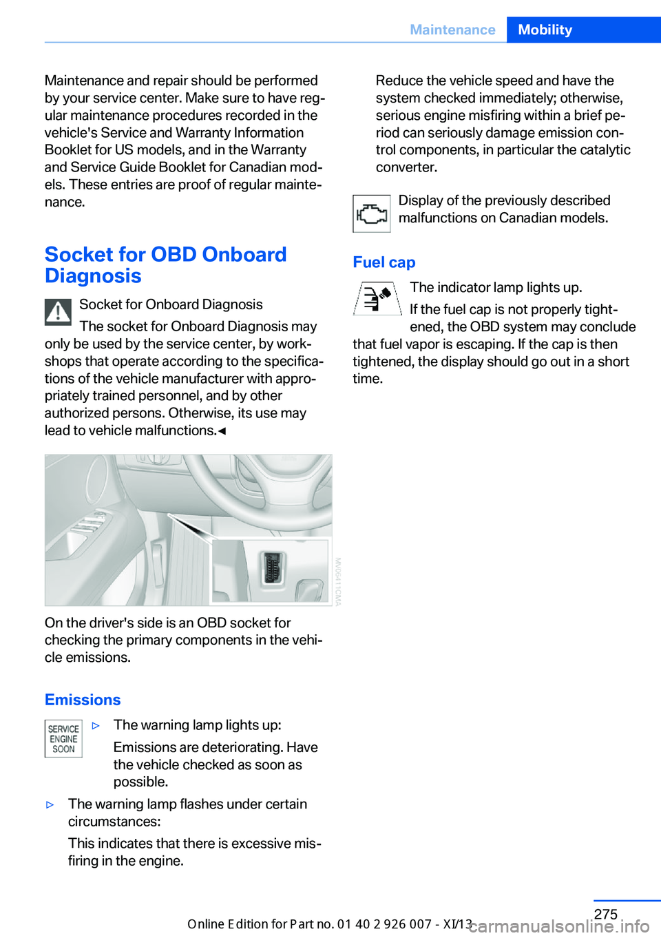
On the driver's side is an OBD socket for
checking the primary components in the vehi‐
cle emissions.
Emissions
▷The warning lamp lights up:
Emissions are deteriorating. Have
the vehicle checked as soon as
possible.▷The warning lamp flashes under certain
circumstances:
This indicates that there is excessive mis‐
firing in the engine.Reduce the vehicle speed and have the
system checked immediately; otherwise,
serious engine misfiring within a brief pe‐
riod can seriously damage emission con‐
trol components, in particular the catalytic
converter.
Display of the previously described
malfunctions on Canadian models.
Fuel cap The indicator lamp lights up.
If the fuel cap is not properly tight‐
ened, the OBD system may conclude
that fuel vapor is escaping. If the cap is then
tightened, the display should go out in a short
time.
Seite 275MaintenanceMobility275
Online Edition for Part no. 01 40 2 910 876 - VII/13
Page 281 of 327

To avoid possible injury or equipment damage
when replacing bulbs, observe any instructions
provided by the bulb manufacturer.◀
Do not perform work/bulb replacement
on xenon headlamps
Have any work on the xenon lighting system,
including bulb replacement, performed only by
a service center.
Due to the high voltage present in the system,
there is the danger of fatal injuries if work is
carried out improperly.◀
Do not touch the bulbs
Do not touch the glass of new bulbs with
your bare hands, as even minute amounts of
contamination will burn into the bulb's surface
and reduce its service life.
Use a clean tissue, cloth or something similar,
or hold the bulb by its base.◀
Light-emitting diodes LED
Light-emitting diodes installed behind translu‐
cent lenses serve as the light source for many
of the controls, displays and other equipment
in your vehicle.
These light-emitting diodes, which operate us‐
ing a concept similar to that applied in conven‐
tional lasers, are officially designated as
Class 1 light-emitting diodes.
Do not remove the covers
Do not remove the covers, and never
stare into the unfiltered light for several hours; otherwise, irritation of the retina could result.◀
Headlamp glass
Condensation can form on the inside of the
headlamps in cool or humid weather. When
you drive with the lights switched on, the con‐
densation evaporates after a short time. The
headlamps do not need to be changed.
If the condensation in the headlamps does not
evaporate after trips with the lights switchedon, and the amount of moisture in the head‐
lamps increases, for example if water droplets
form, have them checked by your service cen‐
ter.
Changing the lamps
Xenon headlamps
Notes
Because of the long life of these bulbs, the
likelihood of failure is very low. Switching the
lamps on and off frequently shortens their life.
If a xenon bulb fails, switch on the front fog
lamps and continue the trip with great care.
Comply with local regulations.
Do not perform work/bulb replacement
on xenon headlamps
Have any work on the xenon lighting system,
including bulb replacement, performed only by
a service center.
Due to the high voltage present in the system,
there is the danger of fatal injuries if work is
carried out improperly.◀
Follow the general instructions on lamps and
bulbs, refer to page 276.
Parking lamps, roadside parking
lamps, daytime running lights
The illustration shows the left side of the en‐
gine compartment.Seite 277Replacing componentsMobility277
Online Edition for Part no. 01 40 2 910 876 - VII/13
Page 283 of 327

Contact your service center in the event of a
malfunction.
Tail lamps▷Turn signal, backup lamp: 21-watt bulb,
H21W.▷Brake lamp, brake force display: 21-watt
bulb, P21W▷Tail lamp: LED technology.
Contact your service center in the event of
a malfunction.
Arrangement of tail lamps
1Tail lamps2Brake force display3Brake lamp4Backup lamp5Turn signal
Brake lamps
Follow the general instructions on lamps and
bulbs, refer to page 276.
1.Open the side panel in the cargo area.2.Remove the first aid kit and warning trian‐
gle if necessary.3.Rotate the relevant bulb socket to the left
and remove.4.Apply gentle pressure to the bulb while
turning it to the left for removal and re‐
placement.5.Install in the reverse order.
Turn signal
Follow the general instructions on lamps and
bulbs, refer to page 276.
1.Open the side panel in the cargo area.2.Remove the first aid kit and warning trian‐
gle if necessary.3.Remove bulb holder along with bulb and
replace.4.Install in the reverse order.
Backup lamp
Follow the general instructions on lamps and
bulbs, refer to page 276.
1.Open the side panel in the cargo area.2.Remove the first aid kit and warning trian‐
gle if necessary.Seite 279Replacing componentsMobility279
Online Edition for Part no. 01 40 2 910 876 - VII/13
Page 284 of 327

3.Remove bulb holder along with bulb and
replace.4.Install in the reverse order.
Brake force display
Follow the general instructions on lamps and
bulbs, refer to page 276.
1.Carefully remove the cover in the tailgate
panel with a screwdriver.2.Rotate the bulb socket to the left and re‐
move.3.Apply gentle pressure to the bulb while
turning it to the left for removal and re‐
placement.4.Insert the bulb socket in the tailgate and
engage it.5.Replace the cover.
License plate lamps
Follow the general instructions on lamps and
bulbs, refer to page 276.
These lamps are made using LED technology.
Contact your service center in the event of a
malfunction.
Center brake lamp Follow the general instructions on lamps and
bulbs, refer to page 276.
This lamp uses LED technology for operation.
Contact your service center in the event of a
malfunction.
Changing wheels
Notes
Your vehicle is equipped with run-flat tires, re‐
fer to page 268, as standard equipment.
They do not need to be replaced immediately
in the event of a puncture.
When mounting new tires or changing from
summer to winter tires or vice versa, use run-
flat tires for your own safety.
Do not rotate the front wheels to the rear or
vice versa, as otherwise the handling charac‐
teristics will be negatively affected.
Suitable tools for changing the wheels are
available from the service center as an acces‐
sory.
Seite 280MobilityReplacing components280
Online Edition for Part no. 01 40 2 910 876 - VII/13
Page 298 of 327

Ensure that the floor mats are securely fas‐
tened again when they are returned after being
removed, such as for cleaning.◀
Floor mats can be removed from the passen‐
ger compartment for cleaning.
When returning the floor mats, secure them
again to prevent slipping.
If the floor carpets are very dirty, clean with a
microfiber cloth and water or a textile cleaner.
To prevent matting of the carpet, rub back and
forth in the direction of travel only.
Sensors/cameras
To clean sensors or cameras, use a cloth mois‐
tened with a small amount of glass cleaner.
Displays/screens
Clean the displays with an anti-static micro‐
fiber cloth.
Cleaning displays
Do not use chemical or household
cleansers.
Keep all fluids and moisture away from the
unit.
Otherwise, they could affect or damage surfa‐
ces or electrical components.
Avoid pressing too hard when cleaning and do
not use abrasive materials; otherwise, damage
can result.◀
Long-term vehicle storage Your service center can advise you on what to
consider when storing the vehicle for longer
than three months.Seite 294MobilityCare294
Online Edition for Part no. 01 40 2 910 876 - VII/13
Page 304 of 327

Short commands for voice activationsystemVehicle equipment
This chapter describes all series equipment as
well as country-specific and special equipment
offered for this model series.Therefore, it also
describes equipment that may not be found in
your vehicle, for instance due to the selected
special equipment or the country version. This
also applies to safety-related functions and
systems.
General information
Instructions for voice activation system, refer
to page 25.To have the available spoken instructions read
out loud: ›Voice commands‹
The following short commands apply to vehi‐
cles equipped with a voice activation system.
They have no function in vehicles in which only
the mobile phone is operated using the voice.
Adjusting
Vehicle
FunctionCommandOpens the main menu.›Main menu‹Open the options.›Options‹Open the settings.›Settings‹Settings on the Control Display.›Control display‹Open the time and date.›Time and date‹Open the language and units.›Language and units‹Open the speed limit.›Speed‹Open the light.›Lighting‹Open the door lock.›Door locks‹Seite 300ReferenceShort commands for voice activation system300
Online Edition for Part no. 01 40 2 910 876 - VII/13
Page 305 of 327

Equipment FunctionCommandOpen the air conditioning settings.›Climate‹Open the Head-up Display.›head up display‹Enable the rear.›Allow rear control‹
Vehicle information
Computer
FunctionCommandOpen the computer.›Onboard info‹Open the trip computer.›Trip computer‹
Vehicle
FunctionCommandOpen the vehicle information.›Vehicle info‹Open the vehicle status.›Vehicle status‹
Navigation
General information
FunctionCommandNavigation menu.›Navigation‹Open the destination entry.›Enter address‹Enter the address.›Enter address‹Enter the town/city.›City‹Enter the country.›State‹Enter the postal code.›Postal Code‹Open destination guidance.›Guidance‹Seite 301Short commands for voice activation systemReference301
Online Edition for Part no. 01 40 2 910 876 - VII/13