2013 BMW X5 XDRIVE 35I PREMIUM ECU
[x] Cancel search: ECUPage 76 of 345
P ParkThe drive wheels are blocked.
P is engaged automatically when the following
conditions are met:▷The driver's door is opened while the en‐
gine is running, the safety belt is not fas‐
tened and neither the brake pedal nor the
accelerator is activated.▷The engine is switched off unless N is en‐
gaged and the remote control is in the igni‐
tion lock.▷The remote control is removed from the ig‐
nition lock.
Before leaving the vehicle, ensure that the
transmission position P is engaged; otherwise,
the vehicle may begin to roll.
Engaging transmission position
▷Transmission position P can only be disen‐
gaged if the engine is running and the
brake pedal is pressed.▷With the vehicle stationary, press on the
brake pedal before shifting out of P or N;
otherwise, the shift command will not be
executed: shift lock.
Press on the brake pedal until you start
driving
To prevent the vehicle from creeping after you
select a driving position, maintain pressure on
the brake pedal until you are ready to start.◀
Engaging transmission positions D, R,
N
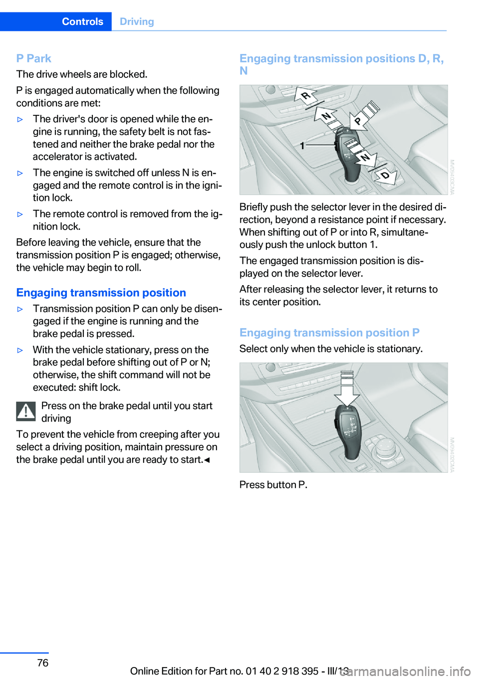
Briefly push the selector lever in the desired di‐
rection, beyond a resistance point if necessary.
When shifting out of P or into R, simultane‐
ously push the unlock button 1.
The engaged transmission position is dis‐
played on the selector lever.
After releasing the selector lever, it returns to
its center position.
Engaging transmission position P Select only when the vehicle is stationary.
Press button P.
Seite 76ControlsDriving76
Online Edition for Part no. 01 40 2 918 395 - III/13
Page 85 of 345

Check Control
The concept The Check Control monitors vehicle functions
and alerts you to any malfunctions in the sys‐
tems monitored.
A Check Control message consists of indicator and warning lamps in the instrument cluster
and, in some circumstances, an acoustic signal
and text messages at the top of the Control
Display.
Indicator/warning lamps
The indicator and warning lamps can light up in
a variety of combinations and colors.
Several of the lamps are checked for proper
functioning and light up temporarily when the
engine is started or the ignition is switched on.
The symbol indicates that Check Control
messages have been stored. The Check Con‐
trol messages can be displayed later.
Text messages Text messages at the upper edge of the Con‐
trol Display in combination with a symbol in the
instrument cluster explain a Check Control
message and the meaning of the indicator and
warning lamps.
Supplementary text messages
Addition information, such as on the cause of a
fault or the required action, can be called up via
Check Control.
In urgent cases, this information will be shown
as soon as the corresponding lamp comes on.
Symbols
The following functions can be selected within
the supplementary text message, depending
on the Check Control message.▷ "Service request"
Contact the service partner.▷ "Roadside Assistance"
Contact Roadside Assistance.
Hiding Check Control messages
Press the button in the turn signal lever up or
down.
▷Some Check Control messages are dis‐
played continuously and are not cleared
until the malfunction is eliminated. If sev‐
eral malfunctions occur at once, the mes‐
sages are displayed consecutively.
These messages can be hidden for approx.
8 seconds. After this time, they are dis‐
played again automatically.▷Other Check Control messages are hidden
automatically after approx. 20 seconds.Seite 85DisplaysControls85
Online Edition for Part no. 01 40 2 918 395 - III/13
Page 139 of 345
Interior equipmentVehicle equipmentThis chapter describes all series equipment as
well as country-specific and special equipment
offered for this model series.Therefore, it also
describes equipment that may not be found in
your vehicle, for instance due to the selected
special equipment or the country version. This
also applies to safety-related functions and
systems.
Universal Garage Door
Opener
The concept The Universal Garage Door Opener can be
used to operate up to 3 functions in remote-
controlled systems, such as garage door drives or lighting systems. The Universal Garage
Door Opener replaces up to 3 different hand-
held transmitters. To operate it, the buttons on
the interior rearview mirror must be program‐
med for the desired functions. The hand-held
transmitter for the system is needed for the
programming procedure.
During programming
During programming and before activat‐
ing a device using the Universal Garage Door
Opener, ensure that there are no people, ani‐
mals, or objects in the range of movement of
the remote-controlled device; otherwise, there
is a risk of injury or damage.
Also follow the safety instructions of the hand-
held transmitter.◀
Before selling the vehicle, delete the stored
functions for security reasons.
Compatibility If this symbol is printed on the packag‐
ing or in the operating instructions ofthe system being operated, the system is gen‐
erally compatible with the Universal Garage
Door Opener.
If you have any questions, please contact:▷Your service center.▷www.homelink.com on the Internet.
HomeLink is a registered trademark of John‐
son Controls, Inc.
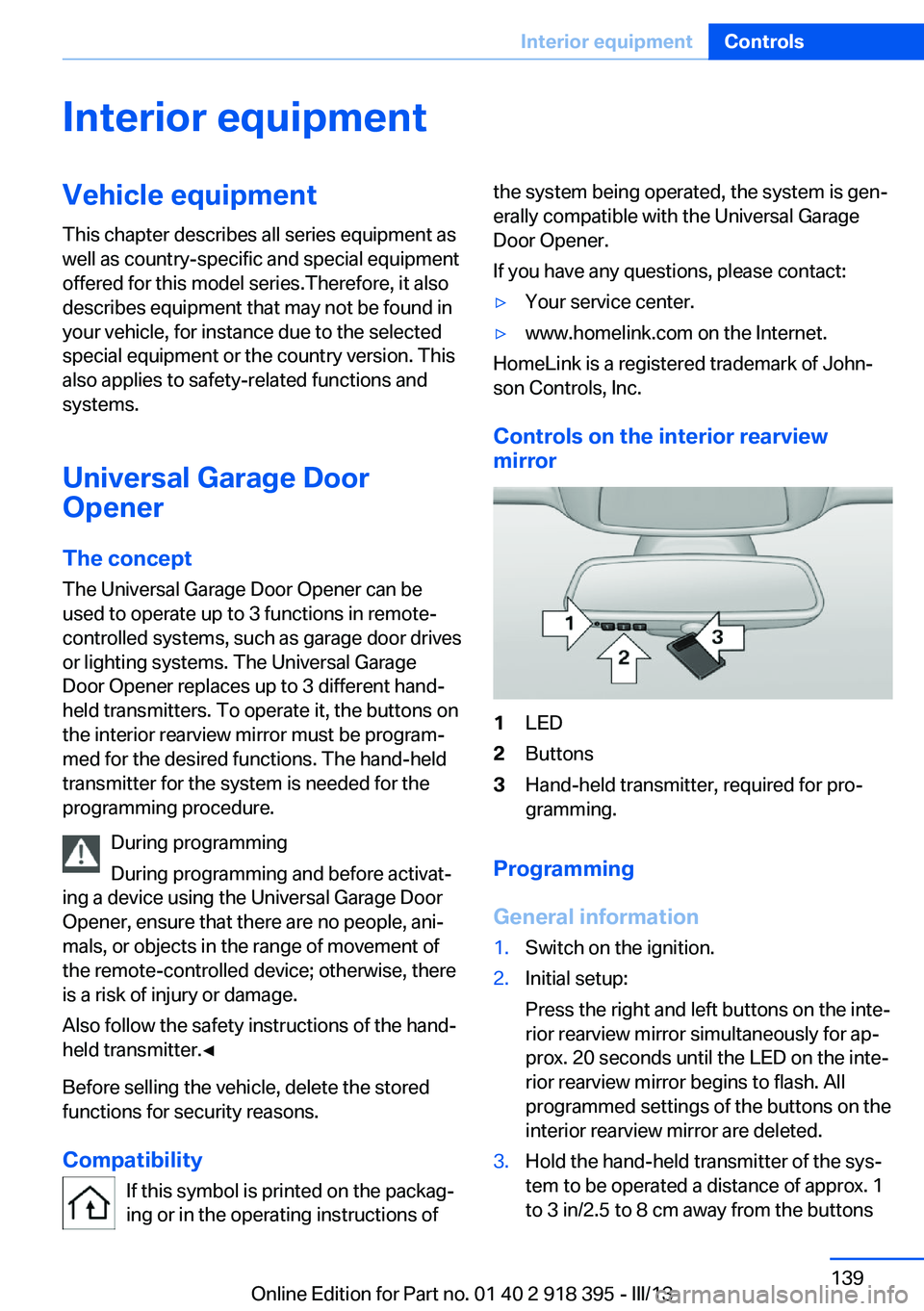
Controls on the interior rearview
mirror
1LED2Buttons3Hand-held transmitter, required for pro‐
gramming.
Programming
General information
1.Switch on the ignition.2.Initial setup:
Press the right and left buttons on the inte‐
rior rearview mirror simultaneously for ap‐
prox. 20 seconds until the LED on the inte‐
rior rearview mirror begins to flash. All
programmed settings of the buttons on the
interior rearview mirror are deleted.3.Hold the hand-held transmitter of the sys‐
tem to be operated a distance of approx. 1
to 3 in/2.5 to 8 cm away from the buttonsSeite 139Interior equipmentControls139
Online Edition for Part no. 01 40 2 918 395 - III/13
Page 140 of 345
on the interior rearview mirror. The re‐
quired distance depends on the particular
hand-held transmitter.4.Press the button of the desired function on
the hand-held transmitter and the button
being programmed on the interior rearview
mirror simultaneously and hold. The LED
on the interior rearview mirror flashes
slowly at first.5.When the LED flashes more rapidly, re‐
lease both buttons. Rapid flashing indi‐
cates that the button on the interior rear‐
view mirror has been programmed.
If the LED does not flash faster after
60 seconds, change the distance between
the interior rearview mirror and the hand-
held transmitter and repeat the step. Multi‐
ple trials at different distances may be nec‐
essary. Wait at least 15 seconds between
trials.6.To program additional functions on other
buttons, repeat steps 3 to 5.
The systems can be operated with the buttons
on the interior rearview mirror.
Special characteristics of alternating-
code radio systems
If the system cannot be operated after re‐
peated programming, check whether the sys‐
tem to be operated uses an alternating-code
system.
Read the operating instructions of the system
or press and hold the programmed button on
the interior rearview mirror. If the LED on the
interior rearview mirror flashes rapidly at first
and then lights up continuously for 2 seconds,
the system is equipped with an alternating-
code system. This flashing LED pattern re‐
peats itself for approx. 20 seconds.
In systems with an alternating-code system,
the Universal Garage Door Opener and the
system must be additionally synchronized.
Please obtain additional information on syn‐
chronization in the operating instructions of
the system being set up.
The systems will be easier to synchronize with
the aid of a second person.
Synchronization:1.Park the vehicle within range of the re‐
mote-controlled system.2.Program the corresponding button on the
interior rearview mirror as described.3.Identify and press the synchronization but‐
ton on the system being set up. You have
approx. 30 seconds for the next step.4.Press and hold the button on the interior
rearview mirror for approx. 3 seconds and
then release it. Repeat this step up to three
times if necessary to complete the syn‐
chronization procedure. When synchroni‐
zation is completed, the programmed func‐
tion is executed.
Reprogramming individual buttons
1.Switch on the ignition.2.Hold the hand-held transmitter at a dis‐
tance of approx. 1 to 3 in/2.5 to 8 cm from
the memory buttons.
The required distance depends on the par‐
ticular hand-held transmitter.3.Press the memory button of the Universal
Garage Door Opener.4.If the LED flashes slowly after approx.
20 seconds, press the transmit button on
the hand-held transmitter.5.Release both buttons when the LED
flashes rapidly.
If the LED does not flash rapidly after ap‐
prox. 60 seconds, change the distance and
repeat the step.
Canada: if the LED does not flash rapidly
after approx. 60 seconds, change the dis‐
tance and repeat the step. If programmingSeite 140ControlsInterior equipment140
Online Edition for Part no. 01 40 2 918 395 - III/13
Page 146 of 345
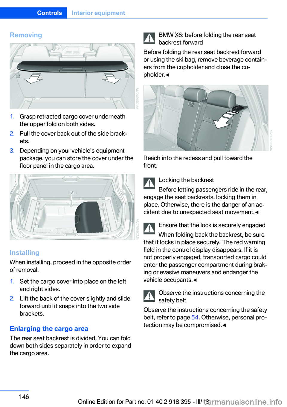
Removing1.Grasp retracted cargo cover underneath
the upper fold on both sides.2.Pull the cover back out of the side brack‐
ets.3.Depending on your vehicle's equipment
package, you can store the cover under the
floor panel in the cargo area.
Installing
When installing, proceed in the opposite order
of removal.
1.Set the cargo cover into place on the left
and right sides.2.Lift the back of the cover slightly and slide
forward until it snaps into the two side
brackets.
Enlarging the cargo area
The rear seat backrest is divided. You can fold
down both sides separately in order to expand
the cargo area.
BMW X6: before folding the rear seat
backrest forward
Before folding the rear seat backrest forward
or using the ski bag, remove beverage contain‐
ers from the cupholder and close the cu‐
pholder.◀
Reach into the recess and pull toward the
front.
Locking the backrest
Before letting passengers ride in the rear,
engage the seat backrests, locking them in
place. Otherwise, there is the danger of an ac‐
cident due to unexpected seat movement.◀
Ensure that the lock is securely engaged
When folding back the backrest, be sure
that it locks in place securely. The red warning
field in the control display disappears. If it is
not properly engaged, transported cargo could
enter the passenger compartment during brak‐
ing or evasive maneuvers and endanger the
vehicle occupants.◀
Observe the instructions concerning the
safety belt
Observe the instructions concerning the safety
belt, refer to page 54. Otherwise, personal pro‐
tection may be compromised.◀
Seite 146ControlsInterior equipment146
Online Edition for Part no. 01 40 2 918 395 - III/13
Page 147 of 345
Storage compartmentsVehicle equipmentThis chapter describes all series equipment as
well as country-specific and special equipment
offered for this model series.Therefore, it also
describes equipment that may not be found in
your vehicle, for instance due to the selected
special equipment or the country version. This
also applies to safety-related functions and
systems.
Notes No loose objects in the passenger com‐
partment
Do not stow any objects in the passenger
compartment without securing them; other‐
wise, they may present a danger to occupants
for instance during braking and avoidance ma‐ neuvers.◀
No non-slip mats on the dashboard
Do not use non-slip materials, such as
non-slip mats, on the dashboard, or it could be
damaged by the substances in the materials.◀Glove compartment
Opening
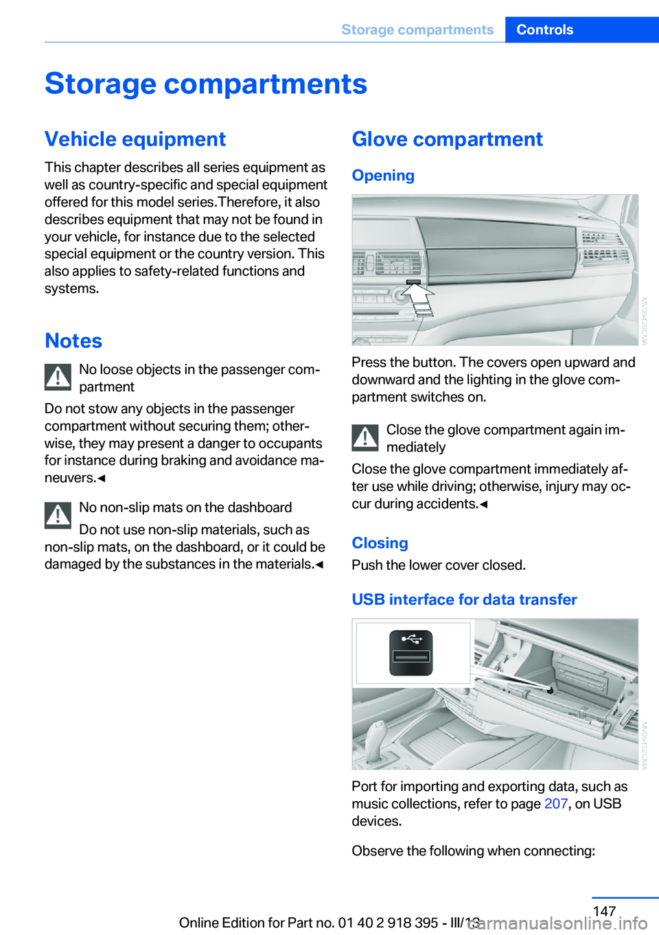
Press the button. The covers open upward and
downward and the lighting in the glove com‐
partment switches on.
Close the glove compartment again im‐
mediately
Close the glove compartment immediately af‐
ter use while driving; otherwise, injury may oc‐
cur during accidents.◀
ClosingPush the lower cover closed.
USB interface for data transfer
Port for importing and exporting data, such as
music collections, refer to page 207, on USB
devices.
Observe the following when connecting:
Seite 147Storage compartmentsControls147
Online Edition for Part no. 01 40 2 918 395 - III/13
Page 150 of 345
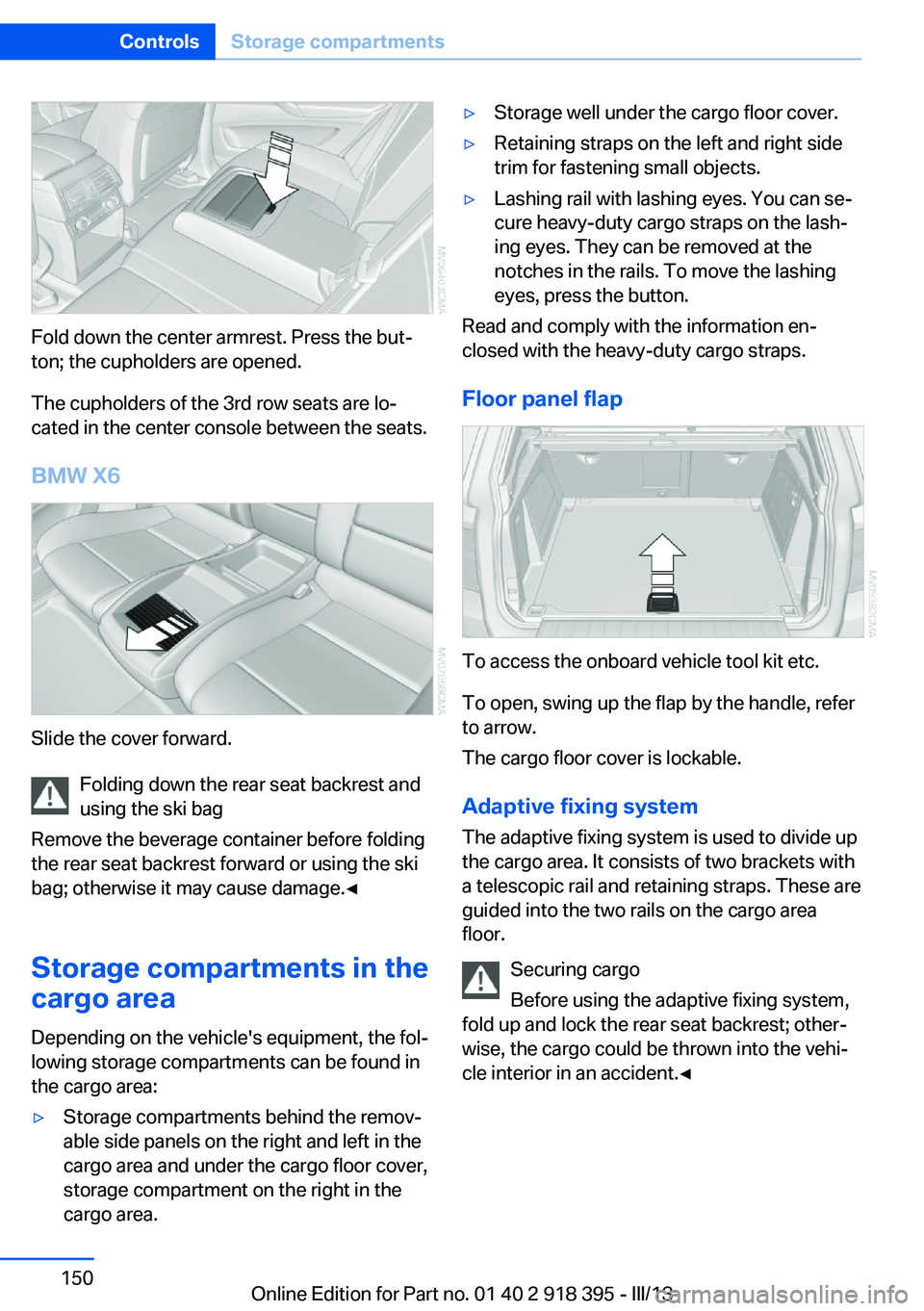
Fold down the center armrest. Press the but‐
ton; the cupholders are opened.
The cupholders of the 3rd row seats are lo‐
cated in the center console between the seats.
BMW X6
Slide the cover forward. Folding down the rear seat backrest and
using the ski bag
Remove the beverage container before folding
the rear seat backrest forward or using the ski
bag; otherwise it may cause damage.◀
Storage compartments in the
cargo area
Depending on the vehicle's equipment, the fol‐
lowing storage compartments can be found in
the cargo area:
▷Storage compartments behind the remov‐
able side panels on the right and left in the
cargo area and under the cargo floor cover,
storage compartment on the right in the
cargo area.▷Storage well under the cargo floor cover.▷Retaining straps on the left and right side
trim for fastening small objects.▷Lashing rail with lashing eyes. You can se‐
cure heavy-duty cargo straps on the lash‐
ing eyes. They can be removed at the
notches in the rails. To move the lashing
eyes, press the button.
Read and comply with the information en‐
closed with the heavy-duty cargo straps.
Floor panel flap
To access the onboard vehicle tool kit etc.
To open, swing up the flap by the handle, refer
to arrow.
The cargo floor cover is lockable.
Adaptive fixing system The adaptive fixing system is used to divide up
the cargo area. It consists of two brackets with
a telescopic rail and retaining straps. These are
guided into the two rails on the cargo area
floor.
Securing cargo
Before using the adaptive fixing system,
fold up and lock the rear seat backrest; other‐
wise, the cargo could be thrown into the vehi‐
cle interior in an accident.◀
Seite 150ControlsStorage compartments150
Online Edition for Part no. 01 40 2 918 395 - III/13
Page 152 of 345
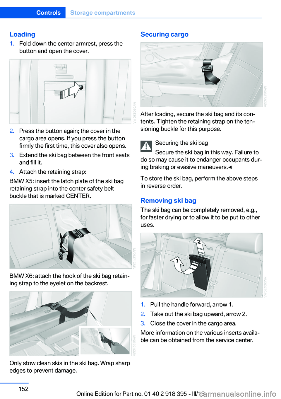
Loading1.Fold down the center armrest, press the
button and open the cover.2.Press the button again; the cover in the
cargo area opens. If you press the button
firmly the first time, this cover also opens.3.Extend the ski bag between the front seats
and fill it.4.Attach the retaining strap:
BMW X5: insert the latch plate of the ski bag
retaining strap into the center safety belt
buckle that is marked CENTER.
BMW X6: attach the hook of the ski bag retain‐
ing strap to the eyelet on the backrest.
Only stow clean skis in the ski bag. Wrap sharp
edges to prevent damage.
Securing cargo
After loading, secure the ski bag and its con‐
tents. Tighten the retaining strap on the ten‐
sioning buckle for this purpose.
Securing the ski bag
Secure the ski bag in this way. Failure to
do so may cause it to endanger occupants dur‐
ing braking or evasive maneuvers.◀
To store the ski bag, perform the above steps
in reverse order.
Removing ski bag
The ski bag can be completely removed, e.g.,
for faster drying or to allow it to be put to other
uses.
1.Pull the handle forward, arrow 1.2.Take out the ski bag upward, arrow 2.3.Close the cover in the cargo area.
More information on the various inserts availa‐
ble can be obtained from the service center.
Seite 152ControlsStorage compartments152
Online Edition for Part no. 01 40 2 918 395 - III/13