2013 BMW X5 XDRIVE 35I turn signal
[x] Cancel search: turn signalPage 240 of 345
nected mobile phone from the vehicle and
pair and connect only one mobile phone.
The mobile phone no longer reacts.
▷Switch the mobile phone off and on again.▷Is the ambient temperature too high or
low? Do not expose the mobile phone to
extreme environmental conditions.
The telephone functions are not available.
▷Is the mobile phone paired as an additional
telephone and is the additional telephone
function deactivated? Activate the func‐
tion.▷Is an outgoing call not possible? Connect
the mobile phone as a telephone.
No phone book entries or only some phone
book entries are displayed, or they are incom‐
plete.
▷Transmission of the phone book entries is
not yet complete.▷It is possible that only the phone book en‐
tries of the mobile phone or the SIM card
are transmitted.▷It may not be possible to display phone
book entries with special characters.▷The number of phone book entries to be
stored is too high.▷Is the data volume of the contact too large,
e. g., due to stored information such as
notes? Reduce the data volume of the con‐
tact.▷Is the mobile phone connected as an audio
source or additional telephone? The mo‐
bile phone must be connected as a tele‐
phone.
The phone connection quality is poor.
▷The strength of the Bluetooth signal on the
mobile phone can be adjusted, depending
on the mobile phone.▷Insert the mobile phone into the snap-in
adapter or place it in the area of the center
console.▷Adjust the volume of the microphone and
loudspeakers separately.
If all points in this list have been checked and
the required function is still not available, con‐
tact Customer Relations or the service center.
Controls
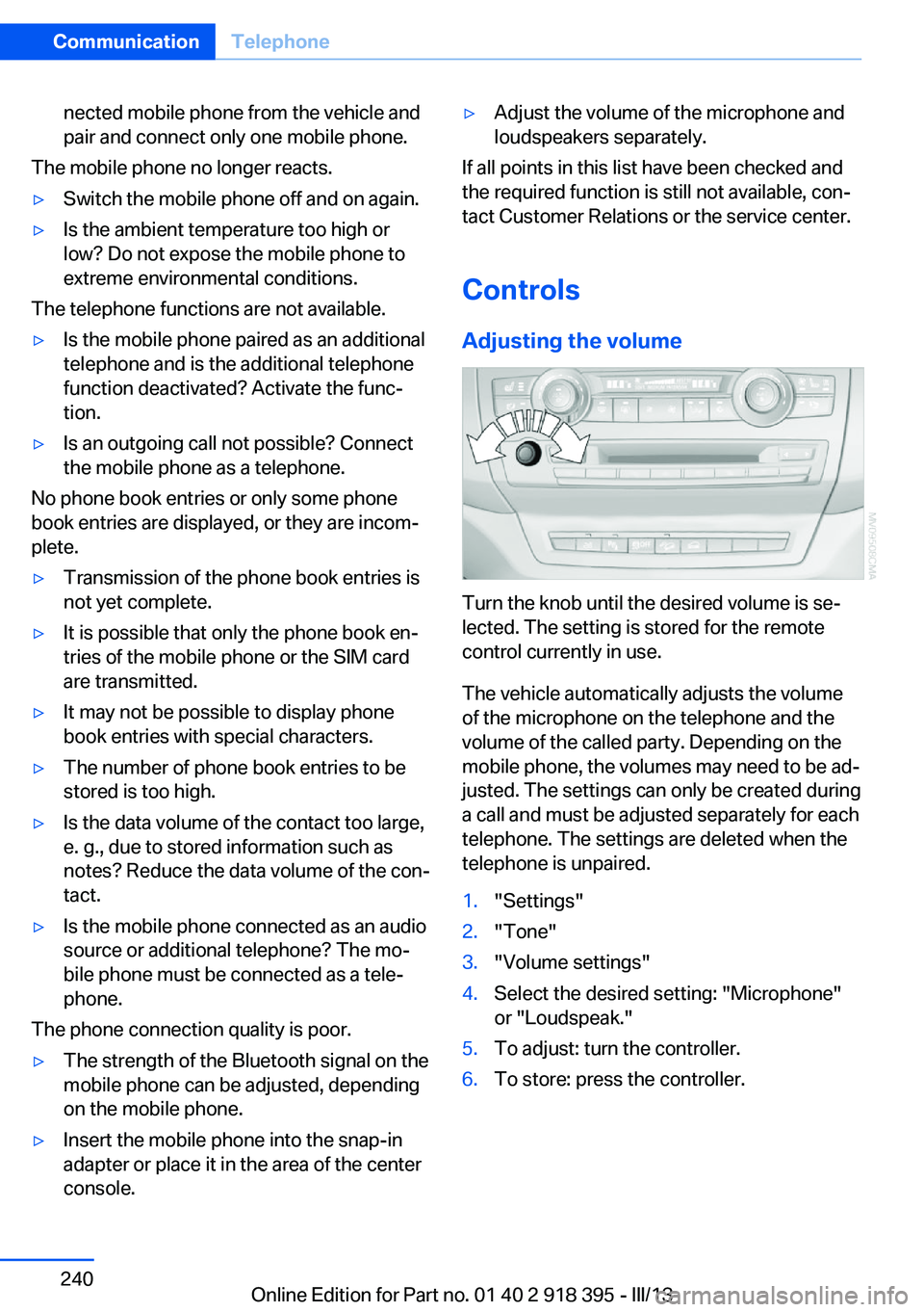
Adjusting the volume
Turn the knob until the desired volume is se‐
lected. The setting is stored for the remote
control currently in use.
The vehicle automatically adjusts the volume
of the microphone on the telephone and the
volume of the called party. Depending on the
mobile phone, the volumes may need to be ad‐
justed. The settings can only be created during
a call and must be adjusted separately for each
telephone. The settings are deleted when the
telephone is unpaired.
1."Settings"2."Tone"3."Volume settings"4.Select the desired setting: "Microphone"
or "Loudspeak."5.To adjust: turn the controller.6.To store: press the controller.Seite 240CommunicationTelephone240
Online Edition for Part no. 01 40 2 918 395 - III/13
Page 242 of 345
If a second call comes in during an ongoing
call, a call waiting signal is sounded.
"Accept"
The call is accepted and the existing call is put
on hold.
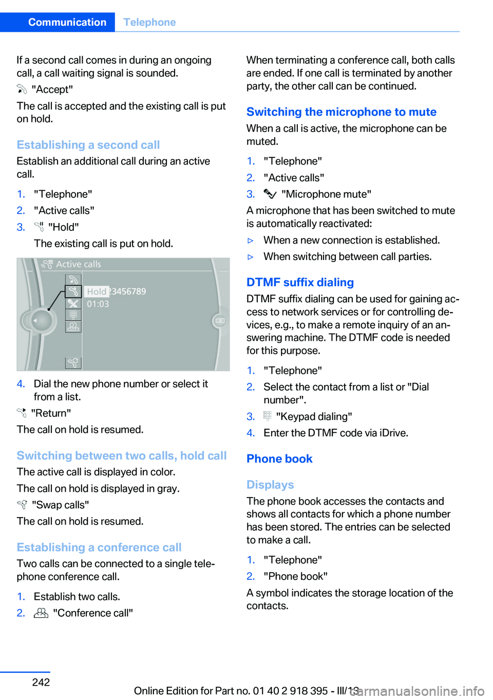
Establishing a second call
Establish an additional call during an active
call.
1."Telephone"2."Active calls"3. "Hold"
The existing call is put on hold.4.Dial the new phone number or select it
from a list.
"Return"
The call on hold is resumed.
Switching between two calls, hold call The active call is displayed in color.
The call on hold is displayed in gray.
"Swap calls"
The call on hold is resumed.
Establishing a conference call Two calls can be connected to a single tele‐
phone conference call.
1.Establish two calls.2. "Conference call"When terminating a conference call, both calls
are ended. If one call is terminated by another
party, the other call can be continued.
Switching the microphone to mute When a call is active, the microphone can be
muted.1."Telephone"2."Active calls"3. "Microphone mute"
A microphone that has been switched to mute
is automatically reactivated:
▷When a new connection is established.▷When switching between call parties.
DTMF suffix dialing
DTMF suffix dialing can be used for gaining ac‐
cess to network services or for controlling de‐
vices, e.g., to make a remote inquiry of an an‐
swering machine. The DTMF code is needed
for this purpose.
1."Telephone"2.Select the contact from a list or "Dial
number".3. "Keypad dialing"4.Enter the DTMF code via iDrive.
Phone book
Displays The phone book accesses the contacts and
shows all contacts for which a phone number
has been stored. The entries can be selected
to make a call.
1."Telephone"2."Phone book"
A symbol indicates the storage location of the
contacts.
Seite 242CommunicationTelephone242
Online Edition for Part no. 01 40 2 918 395 - III/13
Page 297 of 345
Parking lamps, roadside parking
lamps, daytime running lights
These lamps are made using LED technology.
Contact your service center in the event of a
malfunction.
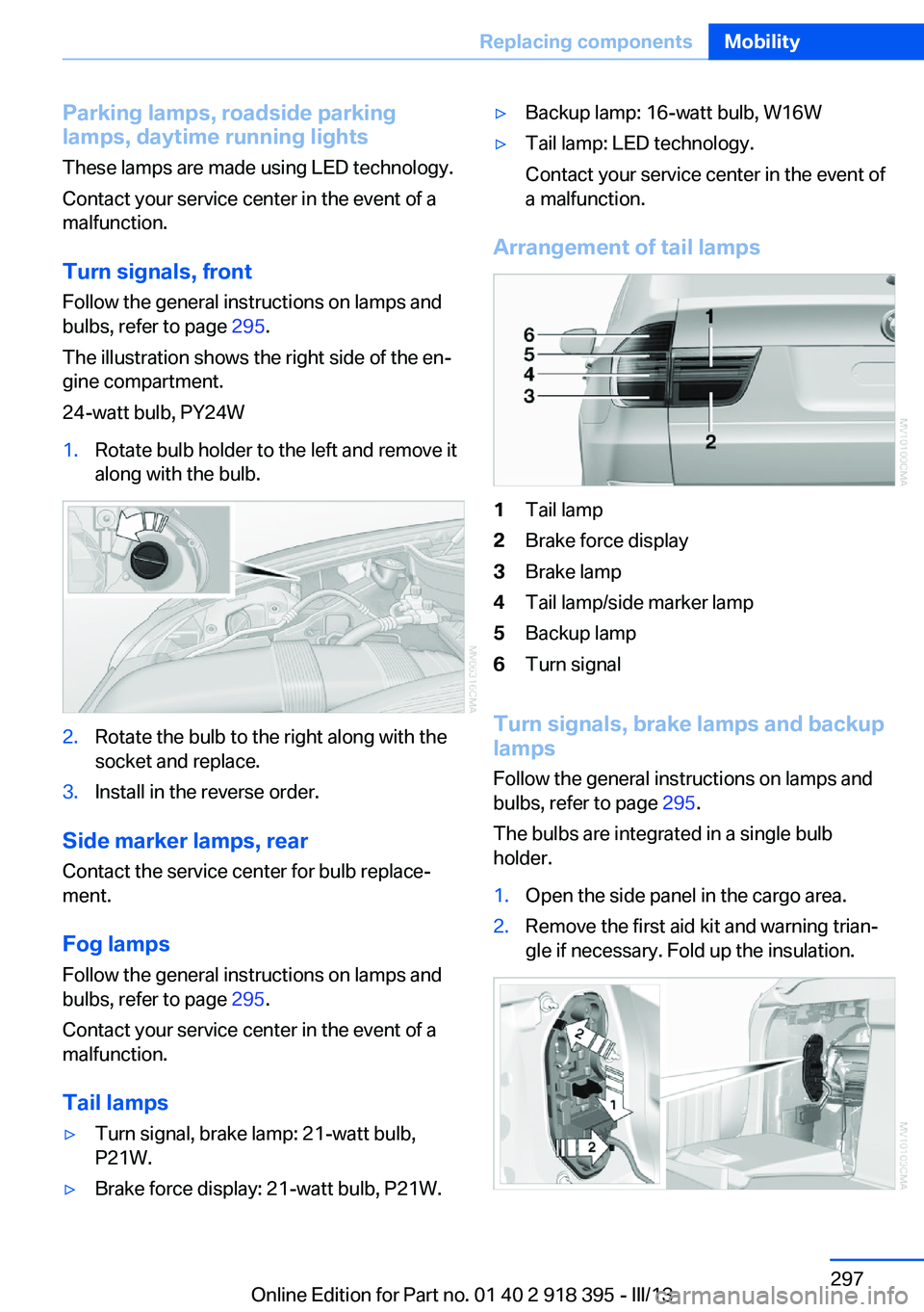
Turn signals, frontFollow the general instructions on lamps and
bulbs, refer to page 295.
The illustration shows the right side of the en‐
gine compartment.
24-watt bulb, PY24W1.Rotate bulb holder to the left and remove it
along with the bulb.2.Rotate the bulb to the right along with the
socket and replace.3.Install in the reverse order.
Side marker lamps, rear
Contact the service center for bulb replace‐
ment.
Fog lamps Follow the general instructions on lamps and
bulbs, refer to page 295.
Contact your service center in the event of a
malfunction.
Tail lamps
▷Turn signal, brake lamp: 21-watt bulb,
P21W.▷Brake force display: 21-watt bulb, P21W.▷Backup lamp: 16-watt bulb, W16W▷Tail lamp: LED technology.
Contact your service center in the event of
a malfunction.
Arrangement of tail lamps
1Tail lamp2Brake force display3Brake lamp4Tail lamp/side marker lamp5Backup lamp6Turn signal
Turn signals, brake lamps and backup
lamps
Follow the general instructions on lamps and
bulbs, refer to page 295.
The bulbs are integrated in a single bulb holder.
1.Open the side panel in the cargo area.2.Remove the first aid kit and warning trian‐
gle if necessary. Fold up the insulation.Seite 297Replacing componentsMobility297
Online Edition for Part no. 01 40 2 918 395 - III/13
Page 300 of 345
▷Daytime running lights.▷Side marker lights.
Contact your service center in the event of a
malfunction.
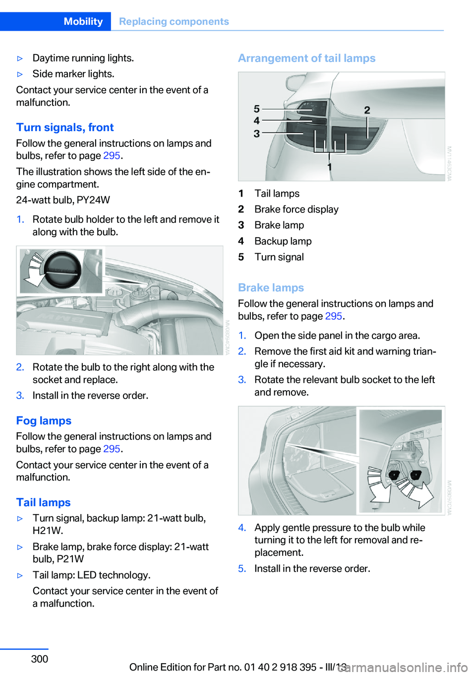
Turn signals, frontFollow the general instructions on lamps and
bulbs, refer to page 295.
The illustration shows the left side of the en‐
gine compartment.
24-watt bulb, PY24W
1.Rotate bulb holder to the left and remove it
along with the bulb.2.Rotate the bulb to the right along with the
socket and replace.3.Install in the reverse order.
Fog lamps
Follow the general instructions on lamps and
bulbs, refer to page 295.
Contact your service center in the event of a
malfunction.
Tail lamps
▷Turn signal, backup lamp: 21-watt bulb,
H21W.▷Brake lamp, brake force display: 21-watt
bulb, P21W▷Tail lamp: LED technology.
Contact your service center in the event of
a malfunction.Arrangement of tail lamps1Tail lamps2Brake force display3Brake lamp4Backup lamp5Turn signal
Brake lamps
Follow the general instructions on lamps and
bulbs, refer to page 295.
1.Open the side panel in the cargo area.2.Remove the first aid kit and warning trian‐
gle if necessary.3.Rotate the relevant bulb socket to the left
and remove.4.Apply gentle pressure to the bulb while
turning it to the left for removal and re‐
placement.5.Install in the reverse order.Seite 300MobilityReplacing components300
Online Edition for Part no. 01 40 2 918 395 - III/13
Page 301 of 345
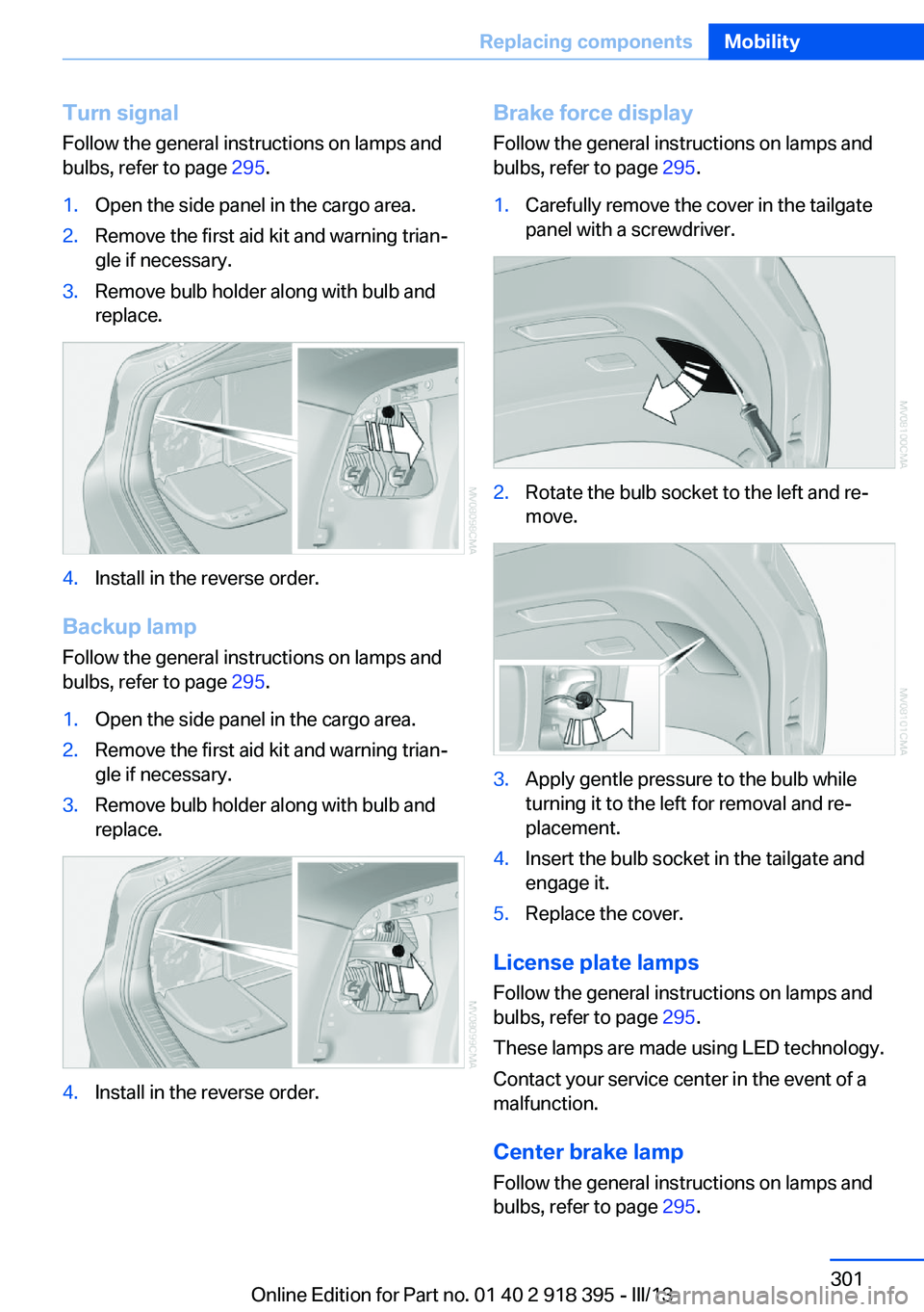
Turn signal
Follow the general instructions on lamps and
bulbs, refer to page 295.1.Open the side panel in the cargo area.2.Remove the first aid kit and warning trian‐
gle if necessary.3.Remove bulb holder along with bulb and
replace.4.Install in the reverse order.
Backup lamp
Follow the general instructions on lamps and
bulbs, refer to page 295.
1.Open the side panel in the cargo area.2.Remove the first aid kit and warning trian‐
gle if necessary.3.Remove bulb holder along with bulb and
replace.4.Install in the reverse order.Brake force display
Follow the general instructions on lamps and
bulbs, refer to page 295.1.Carefully remove the cover in the tailgate
panel with a screwdriver.2.Rotate the bulb socket to the left and re‐
move.3.Apply gentle pressure to the bulb while
turning it to the left for removal and re‐
placement.4.Insert the bulb socket in the tailgate and
engage it.5.Replace the cover.
License plate lamps
Follow the general instructions on lamps and
bulbs, refer to page 295.
These lamps are made using LED technology.
Contact your service center in the event of a
malfunction.
Center brake lamp Follow the general instructions on lamps and
bulbs, refer to page 295.
Seite 301Replacing componentsMobility301
Online Edition for Part no. 01 40 2 918 395 - III/13
Page 333 of 345

Combination instrument, referto Instrument cluster 14
Combination switch, refer to Turn signal/high beams/
headlamp flasher 72
Combination switch, refer to Washer/wiper system 73
Comfort Access– Battery replacement 42
Comfort area, refer to Around
the center console 16
Compact wheel, inflation pressure 275, 276
Compartment for remote control, refer to Ignition
lock 67
Compartments, refer to Stor‐ age compart‐
ments 147, 148
Compass, digital 141
Computer 81
Computer, displaying infor‐ mation 81
Computer, displays on the Control Display 82
Concierge service 261
Condensation on windows, removing 132
Condensation under the vehi‐ cle 158
Condition Based Service CBS 293
Confirmation signals for lock‐ ing/unlocking the vehicle 33
Connecting, mobile phone, refer to Pairing the mobile
phone 237
Consumption, refer to Aver‐ age fuel consumption 82
Contacts 250, 258
Control Display 19
Control Display, care 315
Control Display, setting the brightness 88
Controller, refer to Con‐ trols 18
Controls and displays 12
Controls, rear DVD sys‐
tem 220
Control systems, driving sta‐ bility 105
Convenient operation– Glass sunroof 33– Window 33
Coolant 292
Coolant, checking the level 292
Coolant temperature 80
Cooling function, switching on and off 133
Cooling, maximum 133
Cooling system, refer to Cool‐ ant 292
Cornering Brake Control CBC 105
Corrosion on brake discs 158
Courtesy lamps, refer to Inte‐ rior lamps 94
Cradle for telephone or mo‐ bile phone, refer to Snap-in
adapter 247
Cruise control 118
Cruise control
– Malfunction 119
Cruise control, active 111
Cupholder 149
Curb weight, refer to Weights 320
Current fuel consumption 80
Current location, storing 172
Curve lights, refer to Adaptive Light Control 91
D
Dashboard lighting, refer to Instrument lighting 94
Dashboard, refer to Cock‐ pit 12
Data, technical 318
Date 79
Date, display format 88
Date, retrieving 79
Date, setting 87
Daytime running lights 91
Defroster, rear window 132
Defrosting windows 132
Defrost setting, refer to De‐ frosting windows 132
Destination entry via the ad‐ dress book 172
Destination guidance 179
Destination guidance with in‐ termediate destinations 177
Destination input, naviga‐ tion 170
Diesel exhaust fluid, at low temperatures 272
Diesel exhaust fluid, at mini‐ mum 272
Diesel exhaust fluid, having refilled 272
Diesel exhaust fluid, refilling yourself 272
Diesel particulate filter 157
Digital clock 79
Digital compass 141
Digital radio 193
Dimming mirrors 59
Directional indicators, refer to Turn signals 72
Display in front wind‐ shield 127
Display lighting, refer to In‐ strument lighting 94
Displays and controls 12
Displays, care 315
Displays, cleaning 315
Displays, refer to Instrument cluster 14
Disposal, coolant 292
Disposal, vehicle battery 305
Distance control, refer to Ac‐ tive Cruise Control 111
Distance, selecting, with Ac‐ tive Cruise Control 113
Distance warning, refer to Park Distance Control
PDC 120 Seite 333Everything from A to ZReference333
Online Edition for Part no. 01 40 2 918 395 - III/13
Page 342 of 345

Temperature, adjusting in up‐per body region 132
Temperature, coolant, refer to Coolant temperature 80
Temperature display– External temperature 79– External temperature warn‐
ing 79
Temperature display, setting
the units 88
Temperature, engine oil 80
Temperature, setting with au‐ tomatic climate con‐
trol 132 , 136
Temperature warning 79
Text messages 252
Theft alarm system, refer to Alarm system 42
Thigh support adjustment 49
Third brake lamp, refer to Center brake lamp 298, 301
Seats, 3rd row seats 51
Tilting the passenger side mirror 58
Time, setting 87
Tire age 283
Tire identification marks 283
Tire inflation pressure 275
Tire inflation pressure, check‐ ing 275
Tire pressure monitor, refer to Flat Tire Monitor 97
Tire Pressure Monitor TPM 99
Tire Quality Grading 283
Tires
– Inflation pressure 275
Tires, breaking in 156
Tires, changing 285
Tires, condition 284
Tires, damage 284
Tire size 283
Tires, minimum tread 284
Tires, retreaded tires 286
Tires, run-flat tires 286
Tires, storage 286
Tire tread 284
Toll roads, route 179
Tone 190
Tool kit, refer to Onboard ve‐ hicle tool kit 295
Tools, refer to Onboard vehi‐ cle tool kit 295
Top View 124
Tow bar 310
Tow fitting 310
Towing 309
Town/city, navigation 171
Tow rope 310
Tow-starting 309, 311
TPM Tire Pressure Moni‐ tor 99
Traction control 106
Traffic bulletins, naviga‐ tion 183
Transmission, automatic transmission with Step‐
tronic 75
Transmission positions, auto‐ matic transmission with
Steptronic 75
Transporting children safely 61
Treble, tone 190
Trip computer, refer to Dis‐ plays on the Control Dis‐
play 82
Trip-distance counter, refer to Trip odometer 80
Triple turn signal activa‐ tion 73
Trip odometer 80
Trips, planning 177
Trunk lid, refer to Tailgate 38
Turning circle, refer to Dimen‐ sions 318
Turning lamps, refer to Adap‐ tive Light Control 91
Turn signal, indicator lamp 14
Turn signals 72
Turn signals, triple turn signal activation 73 U
Uniform Tire Quality Grading/ UTQG 283
Unintentional alarms, avoid‐ ing 43
Units, average fuel consump‐ tion 88
Units, temperature 88
Universal Garage Door Opener 139
Universal remote control 139
Unlocking– From the outside 32– Setting the unlocking char‐
acteristics 32– Tailgate 41– Without remote control, re‐
fer to Comfort Access 40
Unlocking, from the inside 35
Unlocking, hood 289
Updates made after the edito‐ rial deadline 6
Update, software 218
Upholstery care 313
Upper tailgate 36
Upper tailgate, automatic op‐ eration 37
Upper tailgate, closing 36
Upper tailgate, emergency operation, refer to Opening
manually 36
Upper tailgate, opening from the inside 36
Upper tailgate, opening from the outside 36
Upper tailgate, opening man‐ ually 36
USB audio interface 212
USB interface 147
V
Vacuum cleaner, connecting, refer to Connecting electri‐
cal devices 143
Seite 342ReferenceEverything from A to Z342
Online Edition for Part no. 01 40 2 918 395 - III/13