2013 BMW X5 XDRIVE 35I service
[x] Cancel search: servicePage 48 of 345

Closing without the pinch protection
system
For example, if there is an external danger, pro‐
ceed as follows:1.Press the switch forward beyond the re‐
sistance point and hold. The pinch protec‐
tion system is limited and the sunroof
opens slightly if the closing force exceeds
a certain value.2.Within about 4 seconds, slide the switch
forward again beyond the resistance point
and hold it there. The roof closes without
the pinch protection system.
Initialization after a power failure
After a power failure, it is only possible to raise
the roof, if necessary.
Have the system initialized by your service
center.
Seite 48ControlsOpening and closing48
Online Edition for Part no. 01 40 2 918 395 - III/13
Page 55 of 345

Unbuckling the belt1.Hold the belt firmly.2.Press the red button in the belt buckle.3.Guide the belt back into its reel.
The shoulder strap's anchorage point will be
correct for adult seat occupants of every build
if the seat is correctly adjusted, refer to
page 49.
The two rear safety belt buckles integrated
into the rear seat are for passengers sitting on
the left and right. The belt buckle embossed
with the word CENTER is intended exclusively
for use by passengers riding in the center posi‐
tion.
Safety belt reminder for the driver's
and front passenger seat
The indicator lamp lights up and a
signal sounds. In addition, a message
appears on the Control Display.
Check whether the safety belt has been fas‐
tened correctly.
The safety belt reminder is active at speeds
above approx. 5 mph/8 km/h. It can also be ac‐
tivated if objects are placed on the front pas‐
senger seat.
Damage to safety belts In the case of strain caused by accidents or
damage:
Have the safety belts, including the safety belt
tensioners, replaced and have the belt anchors
checked.
Checking and replacing safety belts
Have the work performed only by your
service center; otherwise, it cannot be ensured
that this safety feature will function properly.◀
Belt-force limiter
The effect of the belt-force limiter on the driv‐
er's seat is dependent on the position of the
driver's seat.
To maintain the long-term accuracy of this
function, the driver's seat must be calibrated if
a corresponding message is displayed on the
Control Display.
Calibrating driver's seat The warning lamp lights up. A mes‐
sage also appears on the Control Dis‐
play. Please calibrate the driver's
seat.1.Move the driver's seat forward until it
stops.2.Move the driver's seat forward again. It
briefly moves toward the front in the proc‐
ess.3.Set the desired seating position again.
The calibration is completed when the mes‐
sage on the Control Display disappears.
Should this message continue to be displayed,
repeat the calibration. If the message does not
disappear even after repeated calibration, have
the system checked as soon as possible.
Do not carry out calibration while the ve‐
hicle is moving
Never carry out calibration while the vehicle is
moving, as this can cause accidents.
Make sure that no persons or objects become
wedged during the calibration process, as this
can cause injuries or damage.◀
Head restraints Correctly adjusted head restraints
A correctly adjusted head restraint reduces the
risk of spinal injury in the event of an accident.
Adjusting the head restraint
Correctly adjust the head restraints of all
occupied seats; otherwise, there is an in‐
creased risk of injury in an accident.◀
Seite 55AdjustingControls55
Online Edition for Part no. 01 40 2 918 395 - III/13
Page 56 of 345

BMW X5: push the head restraints of the 3rd
row seats into the top position.
Height
Adjust the head restraint so that its center is
approx. at ear level.
Distance Adjust the distance so that the head restraint
is as close as possible to the back of the head.
Active front head restraints
In the event of a rear-end collision of sufficient
severity, the active head restraint reduces the
distance to the head.
Reduced protective function▷Do not use seat or head restraint
covers.▷Do not hang objects, e.g., clothes hangers,
directly on the head restraints.▷Only attach accessories approved by BMW
to the seat or head restraint.
Otherwise, the protective function of the active
head restraint will be impaired and the per‐
sonal safety of the occupants will be endan‐
gered.
Have the active head restraints reset after they
are triggered in a rear-end collision. Have this
work performed by the service center only;
otherwise, this safety feature with not be op‐
erational.◀
Please contact the service center if the front
head restraints need to be removed or instal‐
led.
Front seats: adjusting the height
Adjust the head restraint so that its center is
approx. at ear level.
Electrical
Adjusting electrically.
Front seats: adjusting the distance
from the back of the head
Press the button and pull the headrest cushion
forward or push it back.
Compromised performance
Do not place any objects behind the
headrest cushion. Otherwise, you can impair
the proper function of the head restraint.◀
Comfort seat The distance from the back of the seat occu‐
pant's head can be adjusted using the
shoulder support, refer to page 50.
Seite 56ControlsAdjusting56
Online Edition for Part no. 01 40 2 918 395 - III/13
Page 72 of 345

cargo floor panel, refer to page 295, into
the loop of the release point, see arrow.4.Forcefully pull the screwdriver up against
the mechanical resistance until there is a
marked increase in resistance and the
parking brake can be heard to unlock.5.Stow the screwdriver, warning triangle, and
first aid kit and close the left side panel in
the cargo area.
Have the malfunction corrected
Have the malfunction corrected at the
nearest service center or at a workshop that
works according to BMW repair procedures
with correspondingly trained personnel. If the
parking brake has been released manually in
response to a malfunction, only technicians
can return it to operation.◀
Following manual release, the actual status of
the parking brake may deviate from that dis‐
played by the indicator lamp.
Putting into operation after a power failure
Putting the parking brake into operation
The parking brake should only be put
into operation again if it was manually released
due to an interruption in the supply of electrical
power. Otherwise the operation of the parking
brake is not ensured and there is a danger of
the vehicle rolling despite the parking brake
being set.◀
Procedure1.Switch on the ignition.2.Press the button with the brake depressed.
The indicator lamp in the instrument
cluster goes out as soon as the parking
brake is ready for operation.
Indicator lamp in Canadian models.
Any noises which occur are normal. Startup
may take several seconds.
Turn signal, high beams,
headlamp flasher
At a glance
1High beams2Headlamp flasher3Turn signal
Turn signal
Press the lever beyond the resistance point.
To switch off manually, press the lever to the
resistance point.
Unusually rapid flashing of the indicator lamp
indicates that a turn signal bulb has failed.
Signaling a turn briefly
Press the lever to the resistance point and hold
it there for as long as you want the turn signal
to flash.
Seite 72ControlsDriving72
Online Edition for Part no. 01 40 2 918 395 - III/13
Page 79 of 345

DisplaysVehicle equipmentThis chapter describes all series equipment as
well as country-specific and special equipment
offered for this model series.Therefore, it also
describes equipment that may not be found in
your vehicle, for instance due to the selected
special equipment or the country version. This
also applies to safety-related functions and
systems.
Odometer, external
temperature display, clock1Knob in the instrument cluster2Time, external temperature, and date3Odometer and trip odometer
Knob in the instrument cluster
Press the knob.
▷When the ignition is switched on, the trip
odometer is reset.
Press the knob for approx. 5 seconds:
View service requirement display, refer to
page 83▷When the ignition is switched off, the time,
external temperature and odometer are
displayed.Units of measure
To set the respective units of measure, miles
or km for the odometer and ℃ or ℉ for the ex‐
ternal temperature, refer to page 88.
The setting is stored for the remote control
currently in use.
Time, date, external temperature From radio readiness the external temperature
and the time are displayed.
Set the time, refer to page 87.
Retrieving date
Press the button on turn signal lever upward;
the date appears.
Set the date, refer to page 87.
Pressing the button upward or downward sev‐
eral times changes the display between clock,
external temperature, date, and Check Control
messages, refer to page 85.
External temperature warning If the display drops to +37 ℉/+3 ℃, a signal
sounds and a warning lamp lights up. There is
the increased danger of ice.
Ice on roads
Even at temperatures above
+37 ℉/+3 ℃, there can be a risk of ice on
roads.
Seite 79DisplaysControls79
Online Edition for Part no. 01 40 2 918 395 - III/13
Page 83 of 345

Resetting the trip computerResetting all values:1."Vehicle Info"2."Trip computer"3."Reset"
Service requirements
The remaining driving distance and the date of
the next scheduled service are displayed
briefly immediately after you start the engine
or switch on the ignition.
The current service requirements can be read
out from the remote control by the service
specialist.
For certain maintenance operations, you can
view the distance remaining or the due date for
that operation in the instrument cluster.
1.With the ignition switched on, press the
knob in the instrument cluster, refer to
page 79, for approx. 5 seconds until the
service requirements are displayed.2.Press the knob repeatedly to display the
individual service requirement items.DisplaysSymbolFunctionService requirementsEngine oilRoadworthiness testFront brake padsRear brake padsBrake fluid
The sequence of displayed service items may
vary. First the data for the next maintenance
are displayed.
Seite 83DisplaysControls83
Online Edition for Part no. 01 40 2 918 395 - III/13
Page 84 of 345
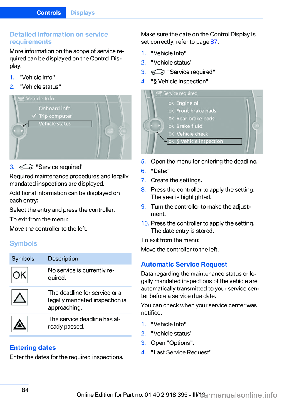
Detailed information on service
requirements
More information on the scope of service re‐
quired can be displayed on the Control Dis‐
play.1."Vehicle Info"2."Vehicle status"3. "Service required"
Required maintenance procedures and legally
mandated inspections are displayed.
Additional information can be displayed on
each entry:
Select the entry and press the controller.
To exit from the menu:
Move the controller to the left.
Symbols
SymbolsDescriptionNo service is currently re‐
quired.The deadline for service or a
legally mandated inspection is
approaching.The service deadline has al‐
ready passed.
Entering dates
Enter the dates for the required inspections.
Make sure the date on the Control Display is
set correctly, refer to page 87.1."Vehicle Info"2."Vehicle status"3. "Service required"4."§ Vehicle inspection"5.Open the menu for entering the deadline.6."Date:"7.Create the settings.8.Press the controller to apply the setting.
The year is highlighted.9.Turn the controller to make the adjust‐
ment.10.Press the controller to apply the setting.
The date entry is stored.
To exit from the menu:
Move the controller to the left.
Automatic Service Request
Data regarding the maintenance status or le‐
gally mandated inspections of the vehicle are
automatically transmitted to your service cen‐
ter before a service due date.
You can check when your service center was
notified.
1."Vehicle Info"2."Vehicle status"3.Open "Options".4."Last Service Request"Seite 84ControlsDisplays84
Online Edition for Part no. 01 40 2 918 395 - III/13
Page 85 of 345

Check Control
The concept The Check Control monitors vehicle functions
and alerts you to any malfunctions in the sys‐
tems monitored.
A Check Control message consists of indicator and warning lamps in the instrument cluster
and, in some circumstances, an acoustic signal
and text messages at the top of the Control
Display.
Indicator/warning lamps
The indicator and warning lamps can light up in
a variety of combinations and colors.
Several of the lamps are checked for proper
functioning and light up temporarily when the
engine is started or the ignition is switched on.
The symbol indicates that Check Control
messages have been stored. The Check Con‐
trol messages can be displayed later.
Text messages Text messages at the upper edge of the Con‐
trol Display in combination with a symbol in the
instrument cluster explain a Check Control
message and the meaning of the indicator and
warning lamps.
Supplementary text messages
Addition information, such as on the cause of a
fault or the required action, can be called up via
Check Control.
In urgent cases, this information will be shown
as soon as the corresponding lamp comes on.
Symbols
The following functions can be selected within
the supplementary text message, depending
on the Check Control message.▷ "Service request"
Contact the service partner.▷ "Roadside Assistance"
Contact Roadside Assistance.
Hiding Check Control messages
Press the button in the turn signal lever up or
down.
▷Some Check Control messages are dis‐
played continuously and are not cleared
until the malfunction is eliminated. If sev‐
eral malfunctions occur at once, the mes‐
sages are displayed consecutively.
These messages can be hidden for approx.
8 seconds. After this time, they are dis‐
played again automatically.▷Other Check Control messages are hidden
automatically after approx. 20 seconds.Seite 85DisplaysControls85
Online Edition for Part no. 01 40 2 918 395 - III/13