2013 BMW X5 XDRIVE 35I height
[x] Cancel search: heightPage 62 of 345

On the front passenger seatAfter installing a child restraint fixing system
on the front passenger seat, ensure that the
front and side airbags on the front passenger
side are deactivated.
Deactivating the front passenger airbags
If a child restraint fixing system is used in
the front passenger seat, the front passenger
airbags must be deactivated; otherwise, there
is an increased risk of injury to the child when
the airbags are triggered, even with a child re‐
straint fixing system.◀
Seat position and height Before installing a child restraint fixing system,
move the front passenger seat as far back as
possible and adjust its height to the highest
position to obtain the best possible position for
the belt and to offer optimal protection in the
event of an accident.
Do not change the seat position and height af‐
ter this.
Backrest width Before mounting a child restraint fixing system
on the front passenger seat, open the backrest
width, refer to page 50, completely. Do not
change the backrest width after this.
Backrest width for the child seat
Before installing a child restraint fixing
system in the front passenger seat, the back‐
rest width must be opened completely. Do not
change the adjustment after this; otherwise,
the stability of the child seat will be reduced.◀Child seat security
The rear safety belts
▷BMW X5: all safety belts of the 2nd and 3rd
row seats▷BMW X6: all safety belts of the 2nd row
seats
And the safety belt for the front passenger can
be locked to prevent extension in order to per‐
mit attachment of child restraint fixing sys‐
tems.
Locking the safety belt
1.Pull out the belt webbing completely.2.Secure the child restraint fixing system
with the belt.3.Allow the belt webbing to be pulled in and
pull it taut against the child restraint fixing
system. The safety belt is locked.
Unlocking the safety belt
1.Open the belt buckle.2.Remove the child restraint fixing system.3.Allow the belt webbing to be pulled in com‐
pletely.
LATCH child restraint fixing
system
LATCH: Lower Anchors and Tether for Chil‐
dren.
Seite 62ControlsTransporting children safely62
Online Edition for Part no. 01 40 2 918 395 - III/13
Page 110 of 345

2.Release the foot brake and drive away
without delay.
Depending on the vehicle load, the vehicle may
roll back slightly.
Driving off without delay
After releasing the foot brake, start driv‐
ing without delay, since the drive-off assistant
will not hold the vehicle in place for more than
approx. 2 seconds and the vehicle will begin
rolling back.◀
Self-leveling suspension The concept The self-leveling suspension on the rear axle
assures a continuous ground clearance.
To do so, the height of the vehicle is measured
by sensors at both rear wheels.
If the actual height deviates from the defined
height, such as due to cargo in the vehicle, this
difference is compensated very quickly. In ad‐
dition, spring motions resulting from cornering
or irregularities in the road surface are reduced
to a minimum.
The system works automatically.
Malfunctions Malfunctions are displayed via Check Control,
refer to page 85.
Active steering The concept
The active steering actively varies the steering
angle of the front wheels in relation to the
steering wheel movements. In addition, it also
varies the steering force required for steering
depending on the vehicle's speed.
When you are driving in the low speed range,
for instance in a town or when parking, the
steering angle increases, i.e., steering be‐
comes very direct. In the higher speed range,
on the other hand, the steering angle is re‐
duced more and more. This improves the han‐
dling of your vehicle over the entire speed
range.
In critical situations, the system can make tar‐
geted corrections to the steering angle pro‐
vided by the driver and thus stabilize the vehi‐
cle before the driver intervenes.
Malfunction The warning lamp lights up yellow
and a message is shown on the Con‐
trol Display. The active steering is de‐
fective or has been temporarily deac‐
tivated. At low speeds, greater steering wheel
movements are required, whereas at higher
speeds, the vehicle reacts more sensitively to
steering wheel movements. The stability-pro‐
moting intervention can also be deactivated.
Proceed cautiously and drive defensively.
Deactivation
Active steering deactivates in order to carry
out an initialization. This deactivation is dis‐
played by means of a message. The initializa‐ tion can take several minutes.
If the message does not disappear during the
current trip, have the system checked.
Defect In the event of a defect, a corresponding text
message is displayed. Have the system
checked.Seite 110ControlsDriving stability control systems110
Online Edition for Part no. 01 40 2 918 395 - III/13
Page 125 of 345

▷Approx. 7 ft/2 m to the side.▷Approx. 7 ft/2 m to the rear.
Obstacles up to the height of the exterior mir‐
rors are thus detected in a timely fashion.
System limits
Top View cannot be used in the following sit‐
uations:
▷With a door open.▷With the tailgate open.▷With an exterior mirror folded in.▷In poor light.
The arrows next to the vehicle are displayed in
a shaded form on the Control Display and a
symbol appears at the corresponding location
on the vehicle.
Check the traffic situation as well
Check the traffic situation around the ve‐
hicle with your own eyes. Otherwise, an acci‐
dent could result from road users or objects lo‐
cated outside the picture area of the
cameras.◀
Switching on automatically
Select transmission position R with the engine
running.
The images from Top View and PDC are dis‐
played when the system has been switched on
using iDrive.
Switching off automatically when
driving forward
The system switches off when a certain dis‐
tance or speed is exceeded.
Switch on the system again if necessary.
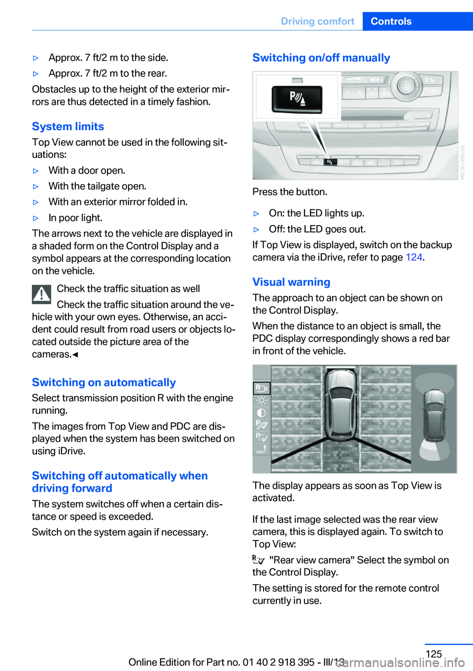
Switching on/off manually
Press the button.
▷On: the LED lights up.▷Off: the LED goes out.
If Top View is displayed, switch on the backup
camera via the iDrive, refer to page 124.
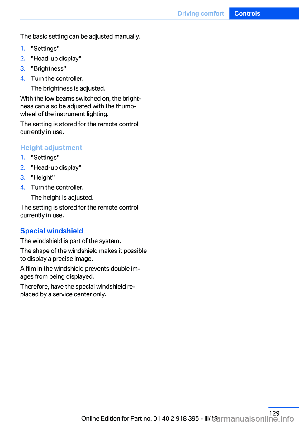
Visual warning
The approach to an object can be shown on
the Control Display.
When the distance to an object is small, the
PDC display correspondingly shows a red bar
in front of the vehicle.
The display appears as soon as Top View is
activated.
If the last image selected was the rear view
camera, this is displayed again. To switch to
Top View:
"Rear view camera" Select the symbol on
the Control Display.
The setting is stored for the remote control
currently in use.
Seite 125Driving comfortControls125
Online Edition for Part no. 01 40 2 918 395 - III/13
Page 129 of 345

The basic setting can be adjusted manually.1."Settings"2."Head-up display"3."Brightness"4.Turn the controller.
The brightness is adjusted.
With the low beams switched on, the bright‐
ness can also be adjusted with the thumb‐
wheel of the instrument lighting.
The setting is stored for the remote control
currently in use.
Height adjustment
1."Settings"2."Head-up display"3."Height"4.Turn the controller.
The height is adjusted.
The setting is stored for the remote control
currently in use.
Special windshield
The windshield is part of the system.
The shape of the windshield makes it possible
to display a precise image.
A film in the windshield prevents double im‐
ages from being displayed.
Therefore, have the special windshield re‐
placed by a service center only.
Seite 129Driving comfortControls129
Online Edition for Part no. 01 40 2 918 395 - III/13
Page 159 of 345

For your own safety and the safety of passen‐
gers and the vehicle, adhere to the following
points:▷Familiarize yourself with the vehicle before
driving; never take risks.▷Adjust speeds according to road condi‐
tions. The steeper and rougher the road
surface is, the lower the speed should be.▷When driving on steep uphill and downhill
grades: the engine oil and coolant should
be filled nearly to the MAX mark.
BMW X5: the vehicle can be driven on up‐
hill and downhill grades up to 50 %.▷Use Hill Descent Control HDC, refer to
page 108, on steep downhill grades.
BMW X5: the vehicle can be driven away
on uphill grades of up to 33 %. The per‐
missible body roll is 50 %.▷Watch for stones, holes, and other obsta‐
cles and drive around these where possi‐
ble.▷On bumps and rough roads, avoid contact
between the vehicle body and the ground.
The maximum ground clearance is 8 in‐
ches/20 cm and may vary with the loaded
cargo.▷When driving through water, do not exceed
the maximum water height.▷BMW X5: 20 inches/50 cm▷BMW X6: 17 inches/45 cm
Drive at walking speed only and do not
stop the vehicle.
▷After driving through water, press on the
brake pedal several times at low speeds to
dry the brakes.▷Depending on the prevailing terrain, acti‐
vate Dynamic Traction Control DTC, refer
to page 106, briefly.▷When the wheels spin, accelerate to ena‐
ble the driving stability control systems to
distribute the drive force to the individual
wheels.▷The stone chip guard reduces the risk of
damage to painted vehicle components,
such as in the area of the side skirts and
wheel arches. Your service center will be
glad to advise you.
After driving on poor roads
Adhere to the following points to ensure vehi‐
cle safety:
▷Remove excessive accumulations of dirt
and mud from the vehicle body.▷Clear mud, snow, ice, etc., from the wheels
and tires and check for damage.Seite 159Things to remember when drivingDriving tips159
Online Edition for Part no. 01 40 2 918 395 - III/13
Page 284 of 345

Temperature
The temperature grades are A, the highest, B,
and C, representing the tire’s resistance to the
generation of heat and its ability to dissipate
heat when tested under controlled conditions
on a specified indoor laboratory test wheel.
Sustained high temperature can cause the ma‐
terial of the tire to degenerate and reduce tire
life, and excessive temperature can lead to
sudden tire failure. The grade C corresponds
to a level of performance which all passenger
car tires must meet under the Federal Motor
Vehicle Safety Standard No. 109. Grades B
and A represent higher levels of performance
on the laboratory test wheel than the minimum
required by law.
Temperature grade for this tire
The temperature grade for this tire is es‐
tablished for a tire that is properly inflated and
not overloaded. Excessive speed, underinfla‐
tion, or excessive loading, either separately or
in combination, can cause heat buildup and
possible tire failure.◀
RSC – Run-flat tires
The symbol identifying run-flat tires is a circle
with the letters RSC on the sidewall, refer to
page 286.
M+S
Winter and all-season tires.
These have better winter properties than
summer tires.
XL
Designation for specially reinforced tires.
Tire treadSummer tires
Do not drive with a tire tread depth of less than
0.12 in/3 mm.There is an increased danger of hydroplaning if
the tread depth is less than 0.12 in/3 mm.
Winter tires Do not drive with a tire tread depth of less than
0.16 in/4 mm.
Below a tread depth of 0.16 in/4 mm, tires are
less suitable for winter operation.
Minimum tread depth
Wear indicators are distributed around the
tire's circumference and have the legally re‐
quired minimum height of 0.063 in/1.6 mm.
They are marked on the side of the tire with
TWI, Tread Wear Indicator.
Tire damage
General information
Inspect your tires often for damage, foreign
objects lodged in the tread, and tread wear.
Notes
Driving over rough or damaged road surfaces,
as well as debris, curbs and other obstacles can cause serious damage to wheels, tires and
suspension parts. This is more likely to occur
with low-profile tires, which provide less cush‐
ioning between the wheel and the road. Be
careful to avoid road hazards and reduce your
speed, especially if your vehicle is equipped
with low-profile tires.
Seite 284MobilityWheels and tires284
Online Edition for Part no. 01 40 2 918 395 - III/13
Page 290 of 345

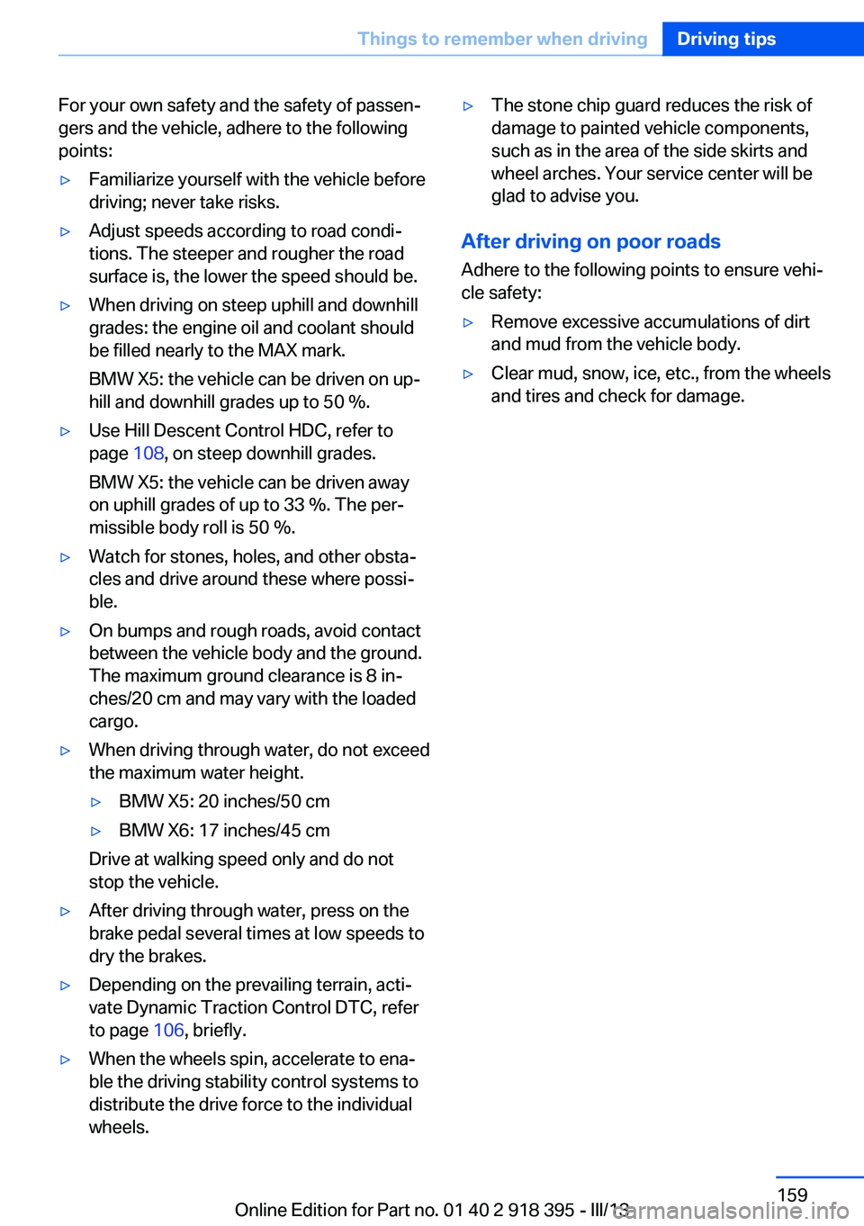
2.Press the release handle and open the
hood.
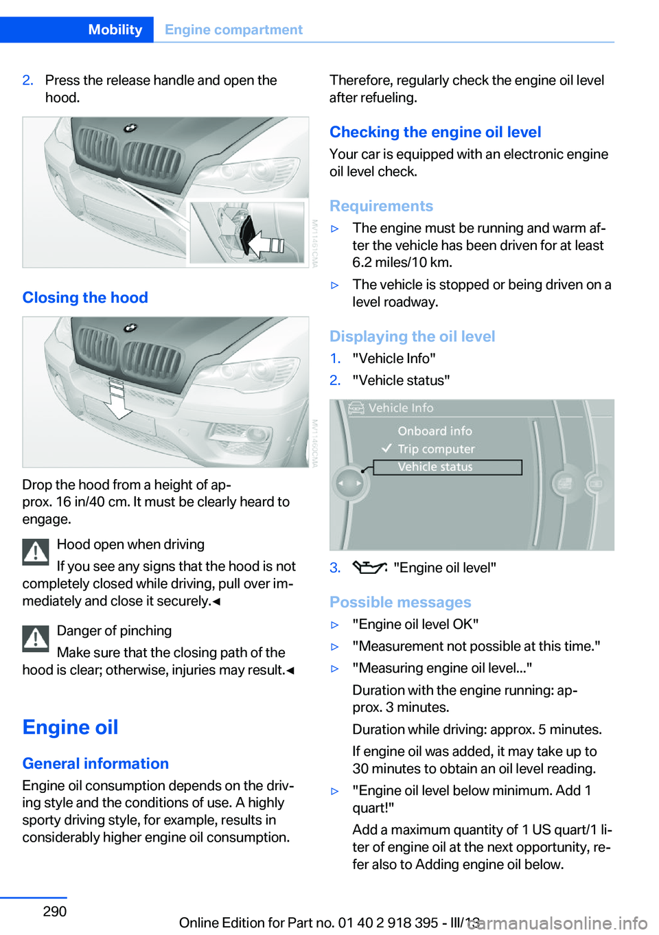
Closing the hood
Drop the hood from a height of ap‐
prox. 16 in/40 cm. It must be clearly heard to
engage.
Hood open when driving
If you see any signs that the hood is not
completely closed while driving, pull over im‐
mediately and close it securely.◀
Danger of pinching
Make sure that the closing path of the
hood is clear; otherwise, injuries may result.◀
Engine oil
General information Engine oil consumption depends on the driv‐
ing style and the conditions of use. A highly
sporty driving style, for example, results in
considerably higher engine oil consumption.
Therefore, regularly check the engine oil level
after refueling.
Checking the engine oil levelYour car is equipped with an electronic engine
oil level check.
Requirements▷The engine must be running and warm af‐
ter the vehicle has been driven for at least
6.2 miles/10 km.▷The vehicle is stopped or being driven on a
level roadway.
Displaying the oil level
1."Vehicle Info"2."Vehicle status"3. "Engine oil level"
Possible messages
▷"Engine oil level OK"▷"Measurement not possible at this time."▷"Measuring engine oil level..."
Duration with the engine running: ap‐
prox. 3 minutes.
Duration while driving: approx. 5 minutes.
If engine oil was added, it may take up to
30 minutes to obtain an oil level reading.▷"Engine oil level below minimum. Add 1
quart!"
Add a maximum quantity of 1 US quart/1 li‐
ter of engine oil at the next opportunity, re‐
fer also to Adding engine oil below.Seite 290MobilityEngine compartment290
Online Edition for Part no. 01 40 2 918 395 - III/13
Page 302 of 345

This lamp uses LED technology for operation.
Contact your service center in the event of a
malfunction.
Changing wheels
Notes Your vehicle is equipped with run-flat tires, re‐
fer to page 286, as standard equipment.
They do not need to be replaced immediately
in the event of a puncture.
When mounting new tires or changing from
summer to winter tires or vice versa, use run-
flat tires for your own safety.
BMW X6: do not rotate the front wheels to the
rear or vice versa, as otherwise the handling
characteristics will be negatively affected.
Suitable tools for changing the wheels are
available from the service center as an acces‐
sory.
Jacking points for the vehicle jack
The jacking points for the vehicle jack are lo‐
cated in the positions shown.
Compact wheel Safety precautions in the event of a flat
tire or wheel change
Park the vehicle as far as possible from pass‐
ing traffic and on solid ground. Switch on the
hazard warning system.
Set the parking brake and engage transmis‐
sion position P.
Have all vehicle occupants get out of the vehi‐
cle and ensure that they remain outside the
immediate area in a safe place, such as behind
a guardrail.
If a warning triangle or portable hazard warning
lamp is required, set it up on the roadside at an
appropriate distance from the rear of the vehi‐
cle. Comply with all safety guidelines and regu‐
lations.
Change the wheel only on a level, firm surface
which is not slippery. The vehicle or the jack
could slip to the side if you attempt to raise the
vehicle on a soft or slippery surface such as
snow, ice, tiles, etc.
Position the jack on a firm support surface.
Do not use a wooden block or similar object as
a support base for the jack, as this would pre‐
vent it from extending to its full support height
and reduce its load-carrying capacity.
To avoid serious or fatal injury: never lie under
the vehicle, and never start the engine while it
is supported by the jack.◀
What you will need
To avoid rattling noises later on, note the posi‐
tions of the tools before removing them, then
return them to their initial positions after com‐
pleting work.
The tools are located in the mount under the
floor panel flap.Seite 302MobilityReplacing components302
Online Edition for Part no. 01 40 2 918 395 - III/13