2013 BMW X5 XDRIVE 35I change time
[x] Cancel search: change timePage 116 of 345
Compliance statement:
This device complies with part 15 of the FCC
Rules. Operation is subject to the following
two conditions:▷This device may not cause harmful inter‐
ference, and▷This device must accept any interference
received, including interference that may
cause undesired operation.
Any unauthorized modifications or changes to
these devices could void the user's authority to
operate this equipment.
System limits
Speed range
Best results are achieved when using the sys‐
tem on well-developed roads and highways.
The desired speed can be selected between
20 mph/30 km/h and 110 mph/180 km/h.
The system can also be activated when sta‐
tionary.
Comply with the legal speed limit in every sit‐
uation when using the system.
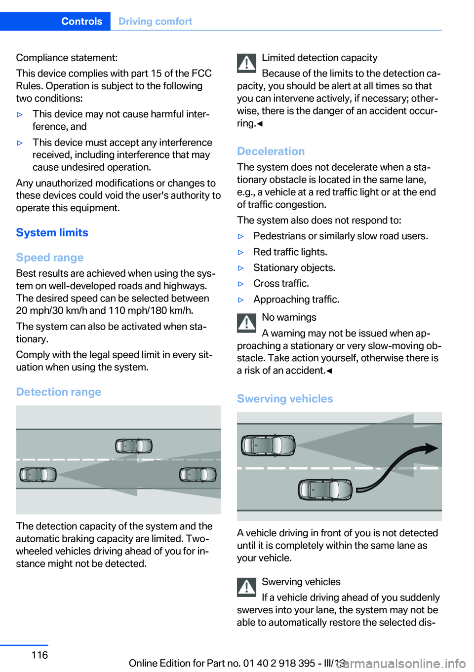
Detection range
The detection capacity of the system and the
automatic braking capacity are limited. Two-
wheeled vehicles driving ahead of you for in‐
stance might not be detected.
Limited detection capacity
Because of the limits to the detection ca‐
pacity, you should be alert at all times so that
you can intervene actively, if necessary; other‐
wise, there is the danger of an accident occur‐
ring.◀
Deceleration
The system does not decelerate when a sta‐
tionary obstacle is located in the same lane,
e.g., a vehicle at a red traffic light or at the end
of traffic congestion.
The system also does not respond to:▷Pedestrians or similarly slow road users.▷Red traffic lights.▷Stationary objects.▷Cross traffic.▷Approaching traffic.
No warnings
A warning may not be issued when ap‐
proaching a stationary or very slow-moving ob‐
stacle. Take action yourself, otherwise there is
a risk of an accident.◀
Swerving vehicles
A vehicle driving in front of you is not detected
until it is completely within the same lane as
your vehicle.
Swerving vehicles
If a vehicle driving ahead of you suddenly
swerves into your lane, the system may not be
able to automatically restore the selected dis‐
Seite 116ControlsDriving comfort116
Online Edition for Part no. 01 40 2 918 395 - III/13
Page 117 of 345
tance. This also applies to major speed differ‐
ences to vehicles driving ahead of you, e.g.,
when rapidly approaching a truck. When a ve‐
hicle driving ahead of you is reliably detected,
the system requests that the driver intervene
by braking and carrying out evasive maneu‐
vers, if necessary. Take action yourself, other‐
wise there is a risk of an accident.◀
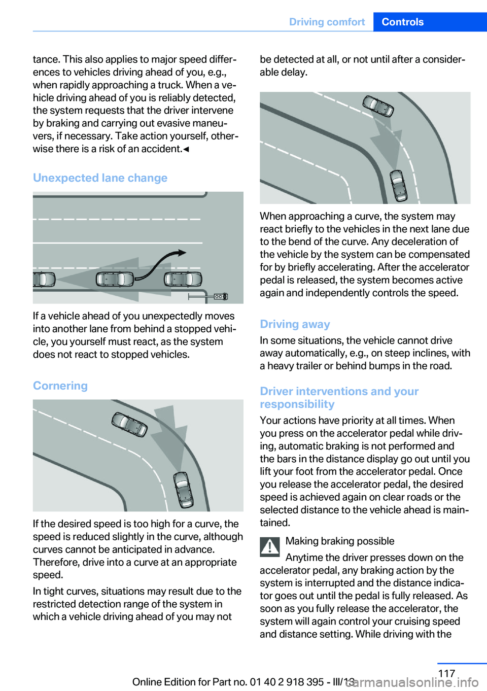
Unexpected lane change
If a vehicle ahead of you unexpectedly moves
into another lane from behind a stopped vehi‐
cle, you yourself must react, as the system
does not react to stopped vehicles.
Cornering
If the desired speed is too high for a curve, the
speed is reduced slightly in the curve, although
curves cannot be anticipated in advance.
Therefore, drive into a curve at an appropriate
speed.
In tight curves, situations may result due to the
restricted detection range of the system in
which a vehicle driving ahead of you may not
be detected at all, or not until after a consider‐
able delay.
When approaching a curve, the system may
react briefly to the vehicles in the next lane due
to the bend of the curve. Any deceleration of
the vehicle by the system can be compensated
for by briefly accelerating. After the accelerator
pedal is released, the system becomes active
again and independently controls the speed.
Driving away In some situations, the vehicle cannot drive
away automatically, e.g., on steep inclines, with
a heavy trailer or behind bumps in the road.
Driver interventions and your
responsibility
Your actions have priority at all times. When
you press on the accelerator pedal while driv‐
ing, automatic braking is not performed and
the bars in the distance display go out until you
lift your foot from the accelerator pedal. Once
you release the accelerator pedal, the desired
speed is achieved again on clear roads or the
selected distance to the vehicle ahead is main‐
tained.
Making braking possible
Anytime the driver presses down on the
accelerator pedal, any braking action by the
system is interrupted and the distance indica‐
tor goes out until the pedal is fully released. As
soon as you fully release the accelerator, the
system will again control your cruising speed
and distance setting. While driving with the
Seite 117Driving comfortControls117
Online Edition for Part no. 01 40 2 918 395 - III/13
Page 119 of 345
The system stores and maintains the speed.
Accelerating using the lever Accelerating slightly:
Press the lever to the resistance point, arrow 1,
until the desired speed is reached.
Accelerating significantly:
Press the lever beyond the resistance point,
arrow 1, until the desired speed is reached.
The vehicle accelerates without pressure on
the accelerator pedal. The system stores and
maintains the speed.
Decreasing speed
Repeatedly pull the lever to the resistance
point or beyond, arrow 2, until the desired
speed is displayed.▷Each time the lever is pulled to the resist‐
ance point, the desired speed is decreased
by approx. 1 mph/1 km/h.▷Each time the lever is pulled beyond the
resistance point, the desired speed is re‐
duced by up to 5 mph/10 km/h until the
minimum speed of 20 mph/30 km/h is ach‐
ieved.
The system stores and maintains the speed.
Interrupting the system
Press the lever up or down, arrow 3: dis‐
play 1 in the speedometer changes color, refer
to page 119.
In addition, the system is interrupted:
▷When the brakes are applied.▷When the transmission position D is disen‐
gaged.▷When DTC is activated or DSC is deacti‐
vated.▷When DSC or ABS is intervening.
Warning lamp
The warning lamp lights up if cruise
control has been deactivated auto‐
matically, e.g., by a control intervention of the
DSC. A message appears on the Control Dis‐
play.
Resuming cruising speed
Press button 4:
The stored speed is resumed and maintained.
Deactivating the system▷Press the lever upward or downward twice,
arrow 3.▷Switch off the ignition.
The stored speed is cleared.
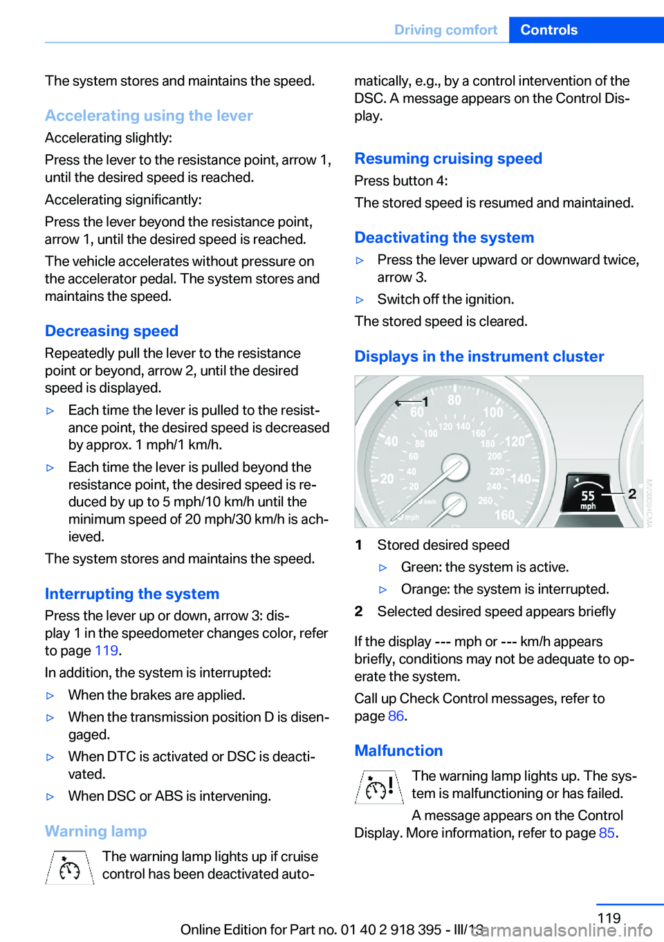
Displays in the instrument cluster
1Stored desired speed▷Green: the system is active.▷Orange: the system is interrupted.2Selected desired speed appears briefly
If the display --- mph or --- km/h appears
briefly, conditions may not be adequate to op‐
erate the system.
Call up Check Control messages, refer to
page 86.
Malfunction The warning lamp lights up. The sys‐
tem is malfunctioning or has failed.
A message appears on the Control
Display. More information, refer to page 85.
Seite 119Driving comfortControls119
Online Edition for Part no. 01 40 2 918 395 - III/13
Page 134 of 345

▷Right LED on, recirculated air mode: the
supply of outside air into the vehicle is per‐
manently blocked.
If the windows are fogged over, switch off the
recirculated-air mode and press the AUTO
button to utilize the condensation sensor.
Make sure that air can flow onto the wind‐
shield.
Continuous recirculated-air mode
The recirculated air mode should not be
used for an extended period of time, as the air
quality inside the vehicle deteriorates stead‐
ily.◀
Residual heat
The heat stored in the engine is used to heat
the interior.
Functional requirement
▷Up to 15 minutes after the engine has been
switched off.▷Warm engine.▷The battery is sufficiently charged.▷External temperature below 77 ℉/25 ℃.
Switching on
1.Switch off the ignition.2.Press the right-hand button.
REST appears on the display of the automatic
climate control when the residual heat utiliza‐
tion is switched on.
From radio readiness the interior temperature,
the air volume and the air distribution can be
set.
Switching off
You can select the lowest blower speed by
pressing and holding the left side. Pressing
again switches off the residual heat utilization.
REST disappears from the display of the auto‐
matic climate control.
Switching on/off the automatic
climate control
Switching off With the blower at its lowest setting,
press the left side of the button to
switch off the automatic climate control.
Switching on Press any button to switch the automatic cli‐mate control back on.
Front ventilation1Use the thumbwheels to smoothly open
and close the air vents2Use the lever to change the direction of the
air flow
Avoiding injury
Do not drop any foreign objects into the
air vents, otherwise these could be catapulted
outwards and lead to injuries.◀
Ventilation for cooling
Adjust the vents to direct the flow of cool air in
your direction, for instance if the interior has
become too warm.
Draft-free ventilation Set the air vents so that the air flows past you
and is not directed straight at you.
Seite 134ControlsClimate134
Online Edition for Part no. 01 40 2 918 395 - III/13
Page 137 of 345
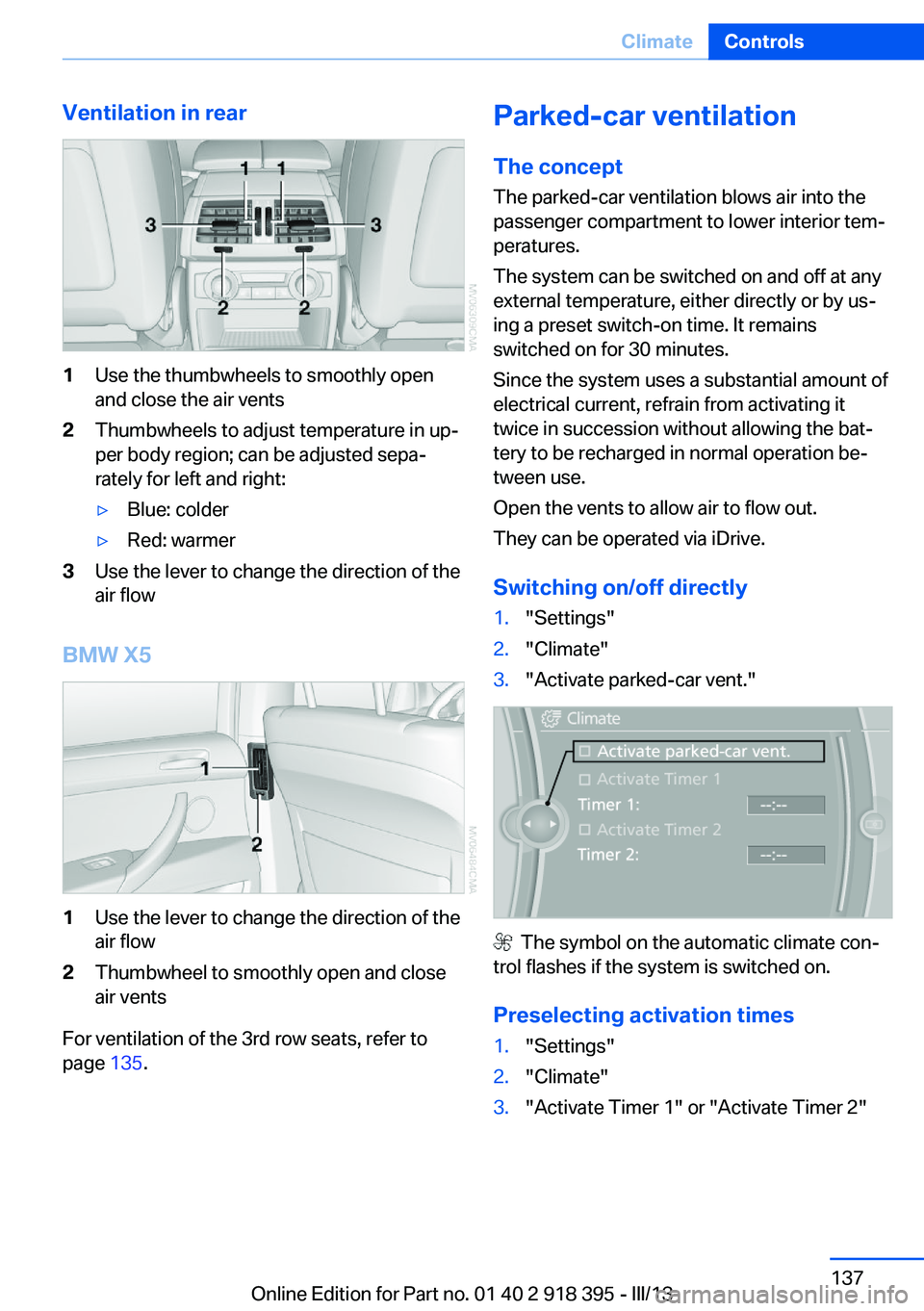
Ventilation in rear1Use the thumbwheels to smoothly open
and close the air vents2Thumbwheels to adjust temperature in up‐
per body region; can be adjusted sepa‐
rately for left and right:▷Blue: colder▷Red: warmer3Use the lever to change the direction of the
air flow
BMW X5
1Use the lever to change the direction of the
air flow2Thumbwheel to smoothly open and close
air vents
For ventilation of the 3rd row seats, refer to
page 135.
Parked-car ventilation
The concept The parked-car ventilation blows air into the
passenger compartment to lower interior tem‐
peratures.
The system can be switched on and off at any
external temperature, either directly or by us‐
ing a preset switch-on time. It remains
switched on for 30 minutes.
Since the system uses a substantial amount of
electrical current, refrain from activating it
twice in succession without allowing the bat‐
tery to be recharged in normal operation be‐
tween use.
Open the vents to allow air to flow out.
They can be operated via iDrive.
Switching on/off directly1."Settings"2."Climate"3."Activate parked-car vent."
The symbol on the automatic climate con‐
trol flashes if the system is switched on.
Preselecting activation times
1."Settings"2."Climate"3."Activate Timer 1" or "Activate Timer 2"Seite 137ClimateControls137
Online Edition for Part no. 01 40 2 918 395 - III/13
Page 140 of 345
on the interior rearview mirror. The re‐
quired distance depends on the particular
hand-held transmitter.4.Press the button of the desired function on
the hand-held transmitter and the button
being programmed on the interior rearview
mirror simultaneously and hold. The LED
on the interior rearview mirror flashes
slowly at first.5.When the LED flashes more rapidly, re‐
lease both buttons. Rapid flashing indi‐
cates that the button on the interior rear‐
view mirror has been programmed.
If the LED does not flash faster after
60 seconds, change the distance between
the interior rearview mirror and the hand-
held transmitter and repeat the step. Multi‐
ple trials at different distances may be nec‐
essary. Wait at least 15 seconds between
trials.6.To program additional functions on other
buttons, repeat steps 3 to 5.
The systems can be operated with the buttons
on the interior rearview mirror.
Special characteristics of alternating-
code radio systems
If the system cannot be operated after re‐
peated programming, check whether the sys‐
tem to be operated uses an alternating-code
system.
Read the operating instructions of the system
or press and hold the programmed button on
the interior rearview mirror. If the LED on the
interior rearview mirror flashes rapidly at first
and then lights up continuously for 2 seconds,
the system is equipped with an alternating-
code system. This flashing LED pattern re‐
peats itself for approx. 20 seconds.
In systems with an alternating-code system,
the Universal Garage Door Opener and the
system must be additionally synchronized.
Please obtain additional information on syn‐
chronization in the operating instructions of
the system being set up.
The systems will be easier to synchronize with
the aid of a second person.
Synchronization:1.Park the vehicle within range of the re‐
mote-controlled system.2.Program the corresponding button on the
interior rearview mirror as described.3.Identify and press the synchronization but‐
ton on the system being set up. You have
approx. 30 seconds for the next step.4.Press and hold the button on the interior
rearview mirror for approx. 3 seconds and
then release it. Repeat this step up to three
times if necessary to complete the syn‐
chronization procedure. When synchroni‐
zation is completed, the programmed func‐
tion is executed.
Reprogramming individual buttons
1.Switch on the ignition.2.Hold the hand-held transmitter at a dis‐
tance of approx. 1 to 3 in/2.5 to 8 cm from
the memory buttons.
The required distance depends on the par‐
ticular hand-held transmitter.3.Press the memory button of the Universal
Garage Door Opener.4.If the LED flashes slowly after approx.
20 seconds, press the transmit button on
the hand-held transmitter.5.Release both buttons when the LED
flashes rapidly.
If the LED does not flash rapidly after ap‐
prox. 60 seconds, change the distance and
repeat the step.
Canada: if the LED does not flash rapidly
after approx. 60 seconds, change the dis‐
tance and repeat the step. If programmingSeite 140ControlsInterior equipment140
Online Edition for Part no. 01 40 2 918 395 - III/13
Page 179 of 345

Destination guidanceVehicle equipmentThis chapter describes all series equipment as
well as country-specific and special equipment
offered for this model series.Therefore, it also
describes equipment that may not be found in
your vehicle, for instance due to the selected
special equipment or the country version. This
also applies to safety-related functions and
systems.
Starting destination
guidance1."Navigation"2.Make a destination entry, refer to
page 170.3."Accept destination"4."Start guidance"
The route is shown on the Control Display.
The distance to the destination/intermediate
destination and the estimated time of arrival
are displayed in the map view.
The arrow view is displayed in the Head-up
Display and in some cases on the Control Dis‐
play.
Terminating destination
guidance
1."Navigation"2."Map"3. "Guidance"4."Stop guidance"Continuing destination
guidance
If the destination was not reached during thelast trip, destination guidance can be resumed.
"Resume guidance"
Route criteria
General information▷The route calculated can be influenced by
selecting certain criteria.▷The route criteria can be changed when
the destination is entered and during desti‐
nation guidance.▷Road types are part of the navigation data
and are taken into consideration when
planning a route, e.g., avoid highways.▷The recommended route may differ from
the route you would take based on per‐
sonal experience.▷The settings are stored for the remote
control currently in use.▷Destination guidance with traffic bulletins,
refer to page 185.
Changing the route criteria
1."Navigation"2."Map"3. "Route preference"4.Select the criterion:▷ "Fast route": time-optimized route,
being a combination of the shortest
possible route and the fastest roads.▷ "ECO PRO route": optimized com‐
bination of the fastest and shortest
route.Seite 179Destination guidanceNavigation179
Online Edition for Part no. 01 40 2 918 395 - III/13
Page 182 of 345
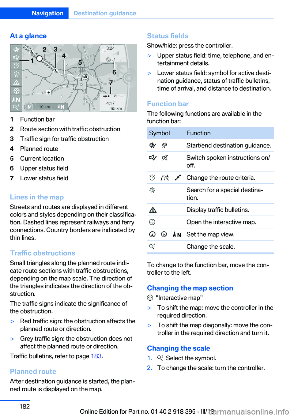
At a glance1Function bar2Route section with traffic obstruction3Traffic sign for traffic obstruction4Planned route5Current location6Upper status field7Lower status field
Lines in the mapStreets and routes are displayed in different
colors and styles depending on their classifica‐ tion. Dashed lines represent railways and ferry
connections. Country borders are indicated by
thin lines.
Traffic obstructions
Small triangles along the planned route indi‐
cate route sections with traffic obstructions,
depending on the map scale. The direction of
the triangles indicates the direction of the ob‐
struction.
The traffic signs indicate the significance of
the obstruction.
▷Red traffic sign: the obstruction affects the
planned route or direction.▷Grey traffic sign: the obstruction does not
affect the planned route or direction.
Traffic bulletins, refer to page 183.
Planned route After destination guidance is started, the plan‐
ned route is displayed on the map.
Status fields
Show/hide: press the controller.▷Upper status field: time, telephone, and en‐
tertainment details.▷Lower status field: symbol for active desti‐
nation guidance, status of traffic bulletins,
time of arrival, and distance to destination.
Function bar
The following functions are available in the
function bar:
SymbolFunction Start/end destination guidance. Switch spoken instructions on/
off. Change the route criteria. Search for a special destina‐
tion. Display traffic bulletins. Open the interactive map. Set the map view. Change the scale.
To change to the function bar, move the con‐
troller to the left.
Changing the map section
"Interactive map"
▷To shift the map: move the controller in the
required direction.▷To shift the map diagonally: move the con‐
troller in the required direction and turn it.
Changing the scale
1. Select the symbol.2.To change the scale: turn the controller.Seite 182NavigationDestination guidance182
Online Edition for Part no. 01 40 2 918 395 - III/13