Page 109 of 211

Warning stagesSymbolMeasureThe vehicle lights up red: prewarn‐
ing.
Increase distance.The vehicle flashes red and an
acoustic signal sounds: acute warn‐
ing.
You are requested to intervene by
braking or making an evasive maneu‐
ver.
Adapting your speed and driving style
The display does not relieve the driver of
the responsibility to adapt his or her driving
speed and style to the traffic conditions.◀
System limits Be alert
Due to system limitations, warnings may
be not be issued at all, or may be issued late or
improperly. Therefore, always be alert and ready
to intervene; otherwise, there is the danger of an
accident occurring.◀
Detection range
The detection capacity of the camera and the
collision warning has limitations.
This may result in the warning not being issued
or being issued late.
For example, the following situations may not be
detected:
▷Slow moving vehicles when you approach
them at high speed.▷Vehicles that suddenly swerve in front of you
or sharply decelerating vehicles.▷Vehicles with an unusual rear appearance.▷Two-wheeled vehicles ahead of you.Functional limitations
The system may not be fully functional in the
following situations:▷In heavy fog, rain, sprayed water or snowfall.▷In tight curves.▷If the camera view field or the front wind‐
shield are dirty or covered.▷When driving toward bright lights.▷In the case of vehicles with insufficiently visi‐
ble tail lamps.▷In the case of partially covered vehicles.▷Up to 10 seconds after the start of the en‐
gine, via the Start/Stop knob.▷During the calibration process of the camera
immediately after vehicle shipment.
Prewarning sensitivity
Depending on the set prewarning time, this may
result in increased false warnings.
Camera
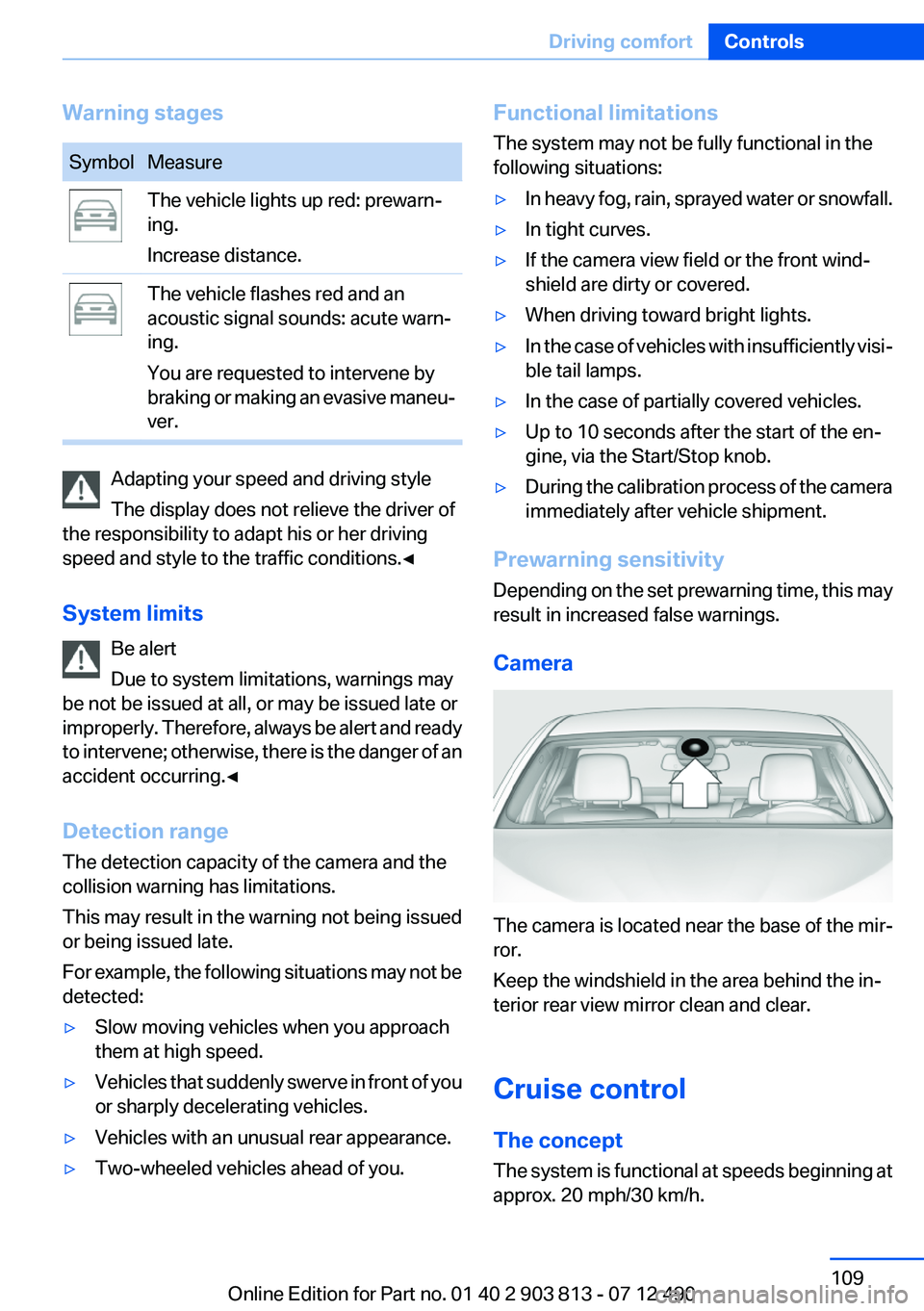
The camera is located near the base of the mir‐
ror.
Keep the windshield in the area behind the in‐
terior rear view mirror clean and clear.
Cruise control
The concept
The system is functional at speeds beginning at
approx. 20 mph/30 km/h.
Seite 109Driving comfortControls109
Online Edition for Part no. 01 40 2 903 813 - 07 12 490
Page 173 of 211

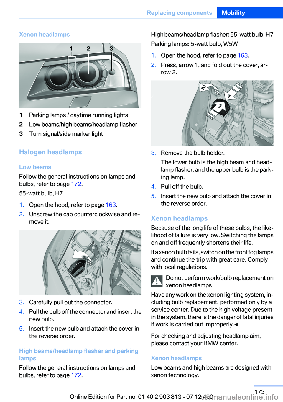
Xenon headlamps1Parking lamps / daytime running lights2Low beams/high beams/headlamp flasher3Turn signal/side marker light
Halogen headlamps
Low beams
Follow the general instructions on lamps and
bulbs, refer to page 172.
55-watt bulb, H7
1.Open the hood, refer to page 163.2.Unscrew the cap counterclockwise and re‐
move it.3.Carefully pull out the connector.4.Pull the bulb off the connector and insert the
new bulb.5.Insert the new bulb and attach the cover in
the reverse order.
High beams/headlamp flasher and parking
lamps
Follow the general instructions on lamps and
bulbs, refer to page 172.
High beams/headlamp flasher: 55-watt bulb, H7
Parking lamps: 5-watt bulb, W5W1.Open the hood, refer to page 163.2.Press, arrow 1, and fold out the cover, ar‐
row 2.3.Remove the bulb holder.
The lower bulb is the high beam and head‐
lamp flasher, and the upper bulb is the park‐
ing lamp.4.Pull off the bulb.5.Insert the new bulb and attach the cover in
the reverse order.
Xenon headlamps
Because of the long life of these bulbs, the like‐
lihood of failure is very low. Switching the lamps
on and off frequently shortens their life.
If a xenon bulb fails, switch on the front fog lamps
and continue the trip with great care. Comply
with local regulations.
Do not perform work/bulb replacement on
xenon headlamps
Have any work on the xenon lighting system, in‐
cluding bulb replacement, performed only by a
service center. Due to the high voltage present
in the system, there is the danger of fatal injuries
if work is carried out improperly.◀
For checking and adjusting headlamp aim,
please contact your BMW center.
Xenon headlamps
Low beams and high beams are designed with
xenon technology.
Seite 173Replacing componentsMobility173
Online Edition for Part no. 01 40 2 903 813 - 07 12 490
Page 174 of 211

The parking lamps and daylight running lights
are made using LED technology.
Contact your service center in the event of a
malfunction.
Front fog lamps
Follow the general instructions on lamps and
bulbs, refer to page 172.
Front fog lamps in vehicles equipped with Adap‐
tive Light Control: 55-watt bulb, H11
Front fog lamps without Adaptive Light Control:
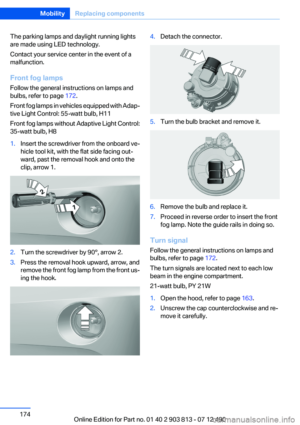
35-watt bulb, H81.Insert the screwdriver from the onboard ve‐
hicle tool kit, with the flat side facing out‐
ward, past the removal hook and onto the
clip, arrow 1.2.Turn the screwdriver by 90°, arrow 2.3.Press the removal hook upward, arrow, and
remove the front fog lamp from the front us‐
ing the hook.4.Detach the connector.5.Turn the bulb bracket and remove it.6.Remove the bulb and replace it.7.Proceed in reverse order to insert the front
fog lamp. Note the guide rails in doing so.
Turn signal
Follow the general instructions on lamps and
bulbs, refer to page 172.
The turn signals are located next to each low
beam in the engine compartment.
21-watt bulb, PY 21W
1.Open the hood, refer to page 163.2.Unscrew the cap counterclockwise and re‐
move it carefully.Seite 174MobilityReplacing components174
Online Edition for Part no. 01 40 2 903 813 - 07 12 490
Page 204 of 211

Direction indicator, refer toTurn signals 65
Display, electronic, instrument cluster 73
Display in windshield 118
Display lighting, refer to Instru‐ ment lighting 89
Displays 72
Displays, cleaning 186
Disposal, coolant 167
Disposal, vehicle battery 177
Distance control, refer to PDC 112
Distance to destination 82
Divided screen view, split screen 21
Door lock, refer to Remote control 30
Downhill control 103
Drive-off assistant, refer to DSC 102
Driving experience switch 105
Driving instructions, breaking in 140
Driving mode 105
Driving notes, general 140
Driving stability control sys‐ tems 102
Driving tips 140
DSC Dynamic Stability Con‐ trol 102
DTC Dynamic Traction Con‐ trol 103
Dynamic Damping Con‐ trol 104
Dynamic Stability Control DSC 102
Dynamic Traction Control DTC 103
E
ECO PRO 147
ECO PRO display 147
ECO PRO mode 147 EfficientDynamics 148
Electronic displays, instru‐ ment cluster 73
Electronic Stability Program ESP, refer to DSC 102
Emergency detection, remote control 31
Emergency release, door lock 36
Emergency release, fuel filler flap 152
Emergency Request 178
Emergency service, refer to Roadside Assistance 179
Emergency start function, en‐ gine start 31
Energy Control 78
Energy recovery 78
Engine, automatic Start/Stop function 61
Engine, automatic switch- off 61
Engine compartment 163
Engine compartment, working in 163
Engine coolant 167
Engine oil 165
Engine oil, adding 166
Engine oil additives 166
Engine oil change 166
Engine oil filler neck 166
Engine oil temperature 76
Engine oil types, alterna‐ tive 166
Engine oil types, ap‐ proved 166
Engine start during malfunc‐ tion 31
Engine start, jump-start‐ ing 179
Engine start, refer to Starting the engine 60
Engine stop 60
Engine temperature 76
Entering a car wash 183
Equipment, interior 127 ESP Electronic Stability Pro‐
gram, refer to DSC 102
Exchanging wheels/tires 160
Exhaust system 140
Exterior mirror, automatic dim‐ ming feature 53
Exterior mirrors 52
External start 179
External temperature dis‐ play 77
External temperature warn‐ ing 77
Eyes for securing cargo 144
F
Failure message, refer to Check Control 74
False alarm, refer to Uninten‐ tional alarm 42
Fan, refer to Air flow 124
Fan, refer to Air volume 121
Fault displays, refer to Check Control 74
Filler neck for engine oil 166
Fine wood, care 185
First aid kit 179
Fitting for towing, refer to Tow fitting 182
Flat tire, changing wheels 176
Flat Tire Monitor FTM 97
Flat tire, Tire Pressure Monitor TPM 94
Flat tire, warning lamp 95, 98
Flooding 141
Floor carpet, care 185
Floor mats, care 185
Fold-out position, windshield wipers 68
Foot brake 141
Front airbags 91
Front fog lamps 89
Front fog lamps, front, bulb re‐ placement 174
Front lamps 172 Seite 204ReferenceEverything from A to Z204
Online Edition for Part no. 01 40 2 903 813 - 07 12 490