2013 BMW X3 XDRIVE 28I ECO mode
[x] Cancel search: ECO modePage 76 of 211
▷ Display additional information about the
Check Control message in the integrated
owner's manual.▷ "Service request"
Contact the service partner.▷ "Roadside Assistance"
Contact Roadside Assistance.
Hiding Check Control messages
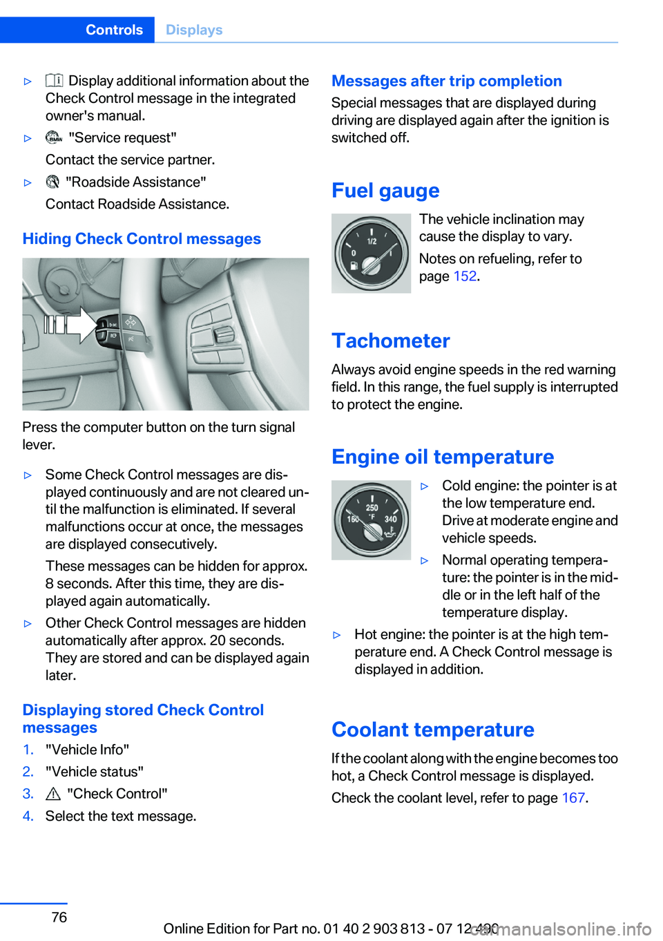
Press the computer button on the turn signal
lever.
▷Some Check Control messages are dis‐
played continuously and are not cleared un‐
til the malfunction is eliminated. If several
malfunctions occur at once, the messages
are displayed consecutively.
These messages can be hidden for approx.
8 seconds. After this time, they are dis‐
played again automatically.▷Other Check Control messages are hidden
automatically after approx. 20 seconds.
They are stored and can be displayed again
later.
Displaying stored Check Control
messages
1."Vehicle Info"2."Vehicle status"3. "Check Control"4.Select the text message.Messages after trip completion
Special messages that are displayed during
driving are displayed again after the ignition is
switched off.
Fuel gauge The vehicle inclination may
cause the display to vary.
Notes on refueling, refer to
page 152.
Tachometer
Always avoid engine speeds in the red warning
field. In this range, the fuel supply is interrupted
to protect the engine.
Engine oil temperature▷Cold engine: the pointer is at
the low temperature end.
Drive at moderate engine and
vehicle speeds.▷Normal operating tempera‐
ture: the pointer is in the mid‐
dle or in the left half of the
temperature display.▷Hot engine: the pointer is at the high tem‐
perature end. A Check Control message is
displayed in addition.
Coolant temperature
If the coolant along with the engine becomes too
hot, a Check Control message is displayed.
Check the coolant level, refer to page 167.
Seite 76ControlsDisplays76
Online Edition for Part no. 01 40 2 903 813 - 07 12 490
Page 86 of 211
LampsVehicle equipment
All standard, country-specific and optional
equipment that is offered in the model series is
described in this chapter. Therefore, equipment
is also described that is not available in a vehicle,
e. g., because of the selected optional equip‐
ment or country variant. This also applies for
safety-related functions and systems.
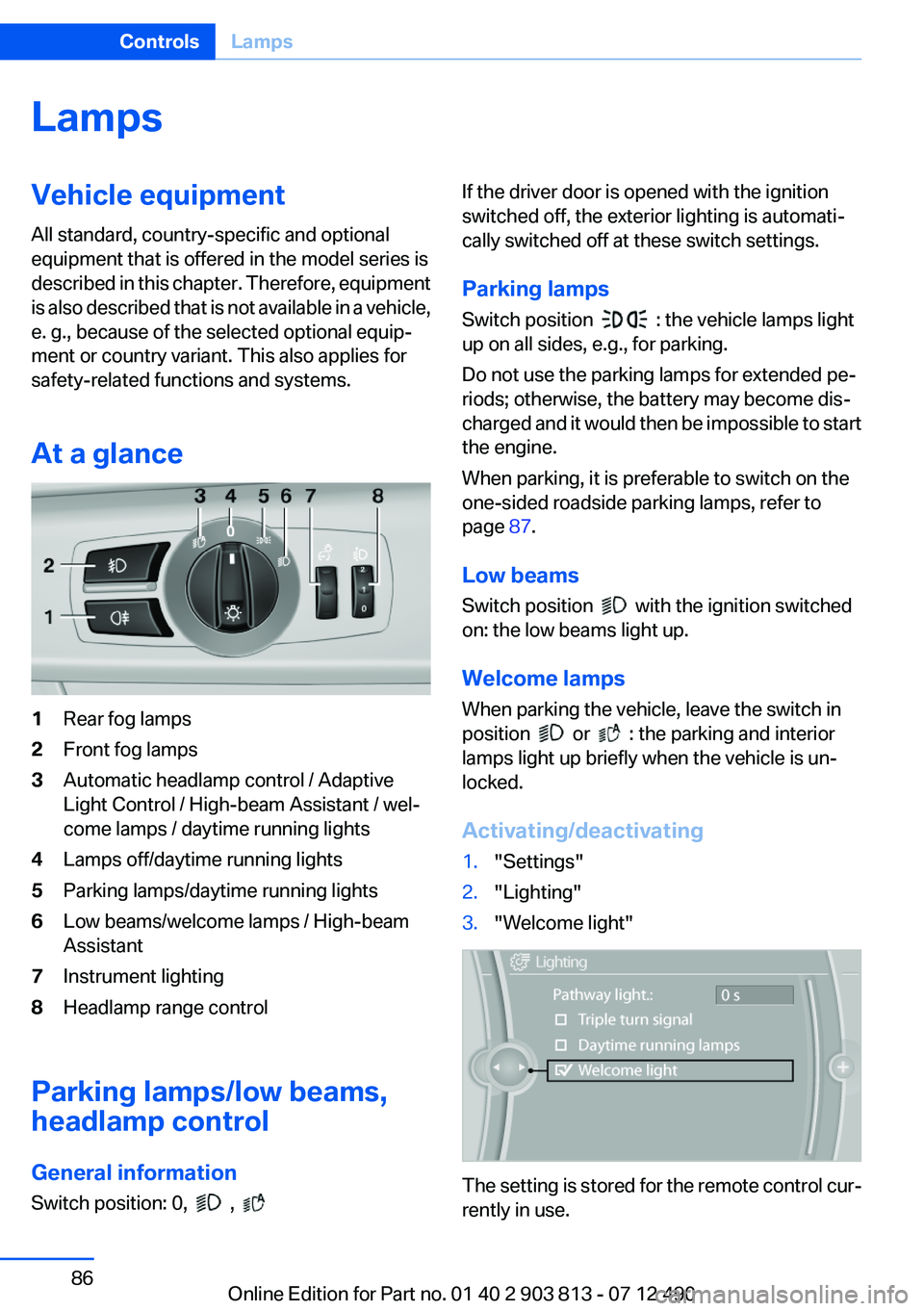
At a glance1Rear fog lamps2Front fog lamps3Automatic headlamp control / Adaptive
Light Control / High-beam Assistant / wel‐
come lamps / daytime running lights4Lamps off/daytime running lights5Parking lamps/daytime running lights6Low beams/welcome lamps / High-beam
Assistant7Instrument lighting8Headlamp range control
Parking lamps/low beams,
headlamp control
General information
Switch position: 0,
,
If the driver door is opened with the ignition
switched off, the exterior lighting is automati‐
cally switched off at these switch settings.
Parking lamps
Switch position
: the vehicle lamps light
up on all sides, e.g., for parking.
Do not use the parking lamps for extended pe‐
riods; otherwise, the battery may become dis‐
charged and it would then be impossible to start
the engine.
When parking, it is preferable to switch on the
one-sided roadside parking lamps, refer to
page 87.
Low beams
Switch position
with the ignition switched
on: the low beams light up.
Welcome lamps
When parking the vehicle, leave the switch in
position
or : the parking and interior
lamps light up briefly when the vehicle is un‐
locked.
Activating/deactivating
1."Settings"2."Lighting"3."Welcome light"
The setting is stored for the remote control cur‐
rently in use.
Seite 86ControlsLamps86
Online Edition for Part no. 01 40 2 903 813 - 07 12 490
Page 102 of 211
Driving stability control systemsVehicle equipment
All standard, country-specific and optional
equipment that is offered in the model series is
described in this chapter. Therefore, equipment
is also described that is not available in a vehicle,
e. g., because of the selected optional equip‐
ment or country variant. This also applies for
safety-related functions and systems.
Antilock Brake System ABS
ABS prevents locking of the wheels during brak‐
ing.
The vehicle remains steerable even during full
brake applications, thus increasing active
safety.
ABS is operational every time you start the en‐
gine.
Brake assistant
When you apply the brakes rapidly, this system
automatically produces the maximum braking
force boost. It thus helps to achieve the shortest
possible braking distance during full braking.
This system utilizes all of the benefits provided
by ABS.
Do not reduce the pressure on the brake pedal
for the duration of the full braking.
DSC Dynamic Stability
Control
The concept
DSC prevents traction loss in the driving wheels
when driving away and accelerating.
DSC also recognizes unstable vehicle condi‐
tions, such as fishtailing or nose-diving. Subjectto physical limits, DSC helps to keep the vehicle
on a steady course by reducing engine speed
and by applying brakes at individual wheels.
Adjust your driving style to the situation
An appropriate driving style is always the
responsibility of the driver.
The laws of physics cannot be repealed, even
with DSC.
Therefore, do not reduce the additional safety
margin by driving in a risky manner.◀
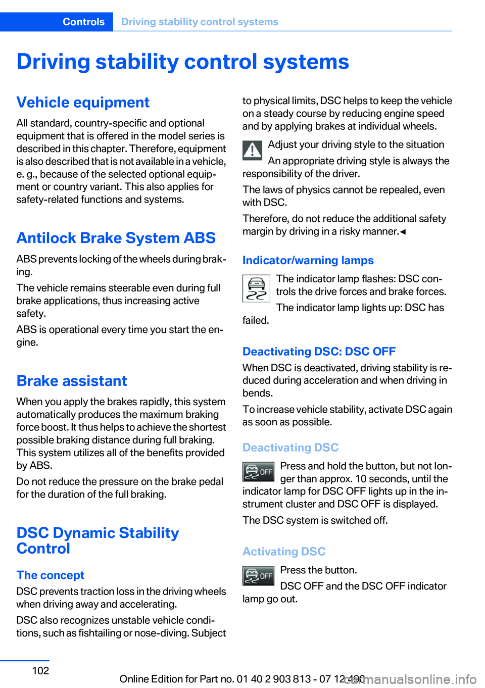
Indicator/warning lamps The indicator lamp flashes: DSC con‐
trols the drive forces and brake forces.
The indicator lamp lights up: DSC has
failed.
Deactivating DSC: DSC OFF
When DSC is deactivated, driving stability is re‐
duced during acceleration and when driving in
bends.
To increase vehicle stability, activate DSC again
as soon as possible.
Deactivating DSC Press and hold the button, but not lon‐
ger than approx. 10 seconds, until the
indicator lamp for DSC OFF lights up in the in‐
strument cluster and DSC OFF is displayed.
The DSC system is switched off.
Activating DSC Press the button.
DSC OFF and the DSC OFF indicator
lamp go out.Seite 102ControlsDriving stability control systems102
Online Edition for Part no. 01 40 2 903 813 - 07 12 490
Page 105 of 211
COMFORT / ECO PRO
Balanced control of the vehicle.
Variable sport steering
The variable sport steering increases the steer‐
ing angle of the front wheels at large steering
wheel angles, e.g., in tight curves or when park‐
ing. Steering becomes more direct.
It also varies the force required to turn the
wheels in accordance with the vehicle speed.
This results in a sporty steering response. In ad‐
dition, it becomes easier to steer during parking
and maneuvering.
Driving Experience Switch
The concept
The Driving Experience Switch can be used to
adjust the certain characteristics of the vehicle.
Various programs can be selected for this pur‐
pose. The Driving Experience Switch and the
DSC OFF buttons can each be used to activate
a program.
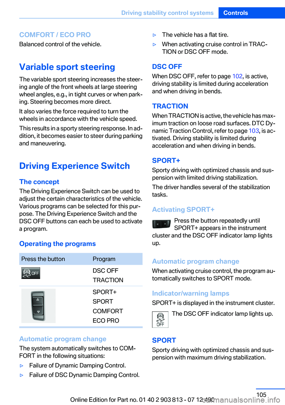
Operating the programsPress the buttonProgramDSC OFF
TRACTIONSPORT+
SPORT
COMFORT
ECO PRO
Automatic program change
The system automatically switches to COM‐
FORT in the following situations:
▷Failure of Dynamic Damping Control.▷Failure of DSC Dynamic Damping Control.▷The vehicle has a flat tire.▷When activating cruise control in TRAC‐
TION or DSC OFF mode.
DSC OFF
When DSC OFF, refer to page 102, is active,
driving stability is limited during acceleration
and when driving in bends.
TRACTION
When TRACTION is active, the vehicle has max‐
imum traction on loose road surfaces. DTC Dy‐
namic Traction Control, refer to page 103, is ac‐
tivated. Driving stability is limited during
acceleration and when driving in bends.
SPORT+
Sporty driving with optimized chassis and sus‐
pension with limited driving stabilization.
The driver handles several of the stabilization
tasks.
Activating SPORT+ Press the button repeatedly until
SPORT+ appears in the instrument
cluster and the DSC OFF indicator lamp lights
up.
Automatic program change
When activating cruise control, the program au‐
tomatically switches to SPORT mode.
Indicator/warning lamps
SPORT+ is displayed in the instrument cluster.
The DSC OFF indicator lamp lights up.
SPORT
Sporty driving with optimized chassis and sus‐
pension with maximum driving stabilization.
Seite 105Driving stability control systemsControls105
Online Edition for Part no. 01 40 2 903 813 - 07 12 490
Page 106 of 211
The program can be configured to individual
specifications. The configuration is stored for
the remote control currently in use.
Activating SPORT Press button repeatedly until SPORT is
displayed in the instrument cluster.
Configuring SPORT
When the display is activated on the Control
Display, refer to page 107, the SPORTdriving
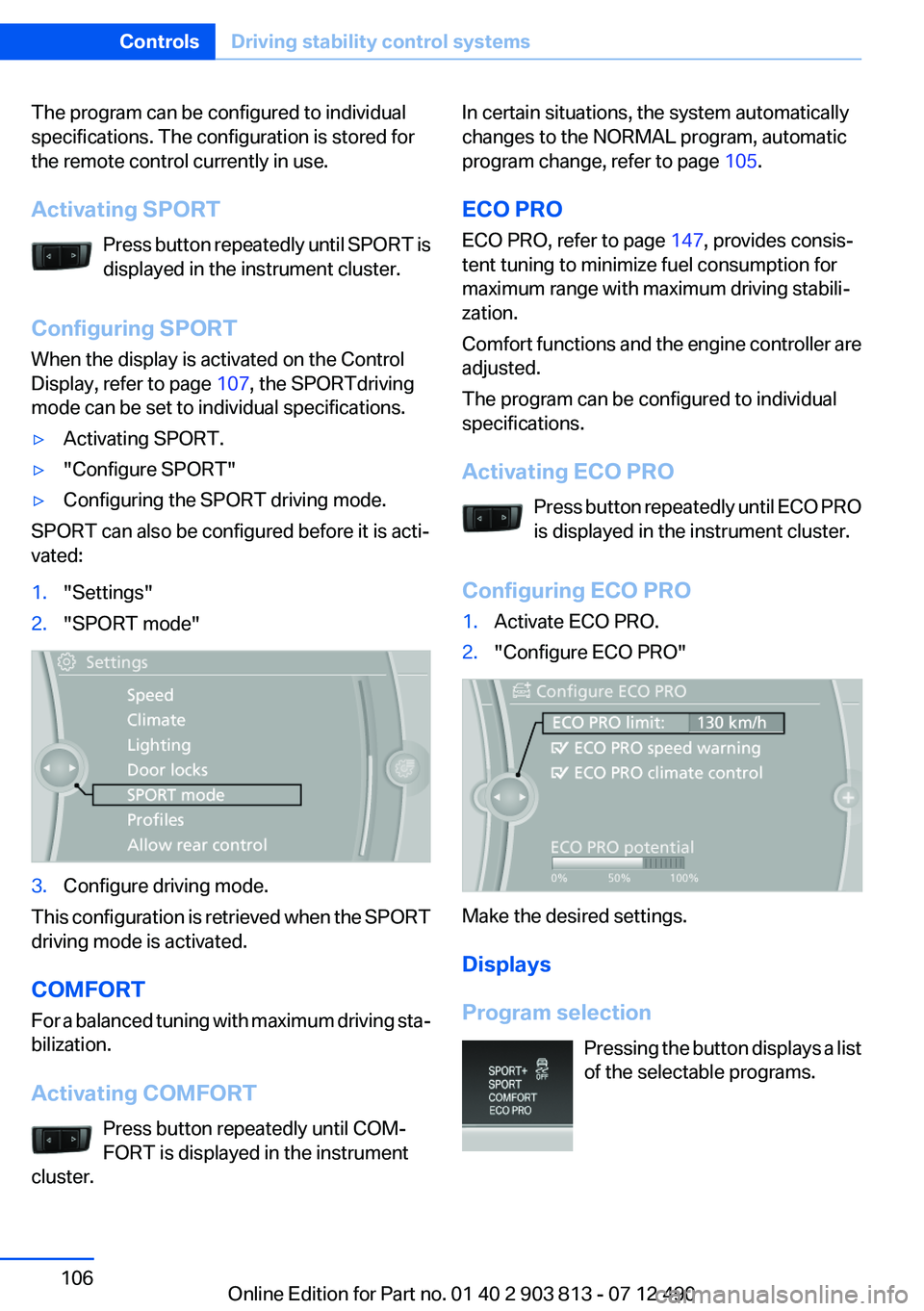
mode can be set to individual specifications.▷Activating SPORT.▷"Configure SPORT"▷Configuring the SPORT driving mode.
SPORT can also be configured before it is acti‐
vated:
1."Settings"2."SPORT mode"3.Configure driving mode.
This configuration is retrieved when the SPORT
driving mode is activated.
COMFORT
For a balanced tuning with maximum driving sta‐
bilization.
Activating COMFORT Press button repeatedly until COM‐
FORT is displayed in the instrument
cluster.
In certain situations, the system automatically
changes to the NORMAL program, automatic
program change, refer to page 105.
ECO PRO
ECO PRO, refer to page 147, provides consis‐
tent tuning to minimize fuel consumption for
maximum range with maximum driving stabili‐
zation.
Comfort functions and the engine controller are
adjusted.
The program can be configured to individual
specifications.
Activating ECO PRO Press button repeatedly until ECO PRO
is displayed in the instrument cluster.
Configuring ECO PRO1.Activate ECO PRO.2."Configure ECO PRO"
Make the desired settings.
Displays
Program selection Pressing the button displays a list
of the selectable programs.
Seite 106ControlsDriving stability control systems106
Online Edition for Part no. 01 40 2 903 813 - 07 12 490
Page 127 of 211
Interior equipmentVehicle equipment
All standard, country-specific and optional
equipment that is offered in the model series is
described in this chapter. Therefore, equipment
is also described that is not available in a vehicle,
e. g., because of the selected optional equip‐
ment or country variant. This also applies for
safety-related functions and systems.
Integrated universal remote
control
The concept
The integrated universal remote control can op‐
erate up to 3 functions of remote-controlled sys‐
tems such as garage door drives or lighting sys‐
tems. The integrated universal remote control
replaces up to 3 different hand-held transmit‐
ters. To operate the remote control, the buttons
on the interior rearview mirror must be program‐
med with the desired functions. The hand-held
transmitter for the particular system is required
in order to program the remote control.
During programming
During programming and before activat‐
ing a device using the integrated universal re‐
mote control, ensure that there are no people,
animals, or objects in the range of movement of
the remote-controlled device; otherwise, there
is a risk of injury or damage.
Also follow the safety instructions of the hand-
held transmitter.◀
Before selling the vehicle, delete the stored
functions for the sake of security.
Compatibility If this symbol is printed on the packaging
or in the instructions of the system to be
controlled, the system is generally com‐patible with the integrated universal remote
control.
If you have any questions, please contact:▷Your service center.▷www.homelink.com on the Internet.
HomeLink is a registered trademark of Johnson
Controls, Inc.
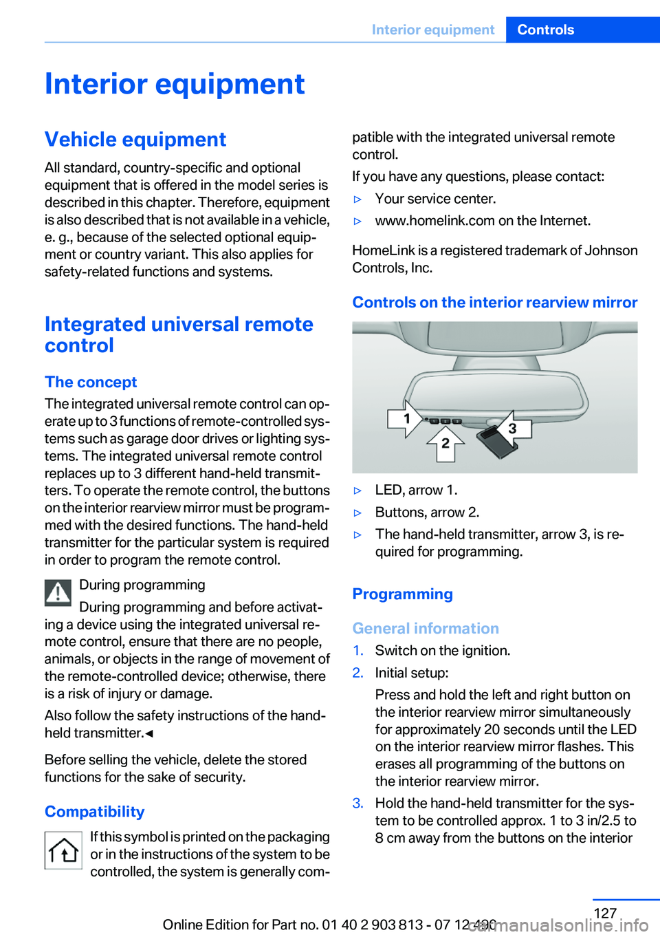
Controls on the interior rearview mirror
▷LED, arrow 1.▷Buttons, arrow 2.▷The hand-held transmitter, arrow 3, is re‐
quired for programming.
Programming
General information
1.Switch on the ignition.2.Initial setup:
Press and hold the left and right button on
the interior rearview mirror simultaneously
for approximately 20 seconds until the LED
on the interior rearview mirror flashes. This
erases all programming of the buttons on
the interior rearview mirror.3.Hold the hand-held transmitter for the sys‐
tem to be controlled approx. 1 to 3 in/2.5 to
8 cm away from the buttons on the interiorSeite 127Interior equipmentControls127
Online Edition for Part no. 01 40 2 903 813 - 07 12 490
Page 140 of 211
Things to remember when drivingVehicle equipment
All standard, country-specific and optional
equipment that is offered in the model series is
described in this chapter. Therefore, equipment
is also described that is not available in a vehicle,
e. g., because of the selected optional equip‐
ment or country variant. This also applies for
safety-related functions and systems.
Breaking-in period
General information
Moving parts need to be broken in to adjust to
each other.
The following instructions will help achieve a
long vehicle life and good economy.
Engine and differential
Always obey the official speed limit.
Up to 1,200 miles/2,000 km
Do not exceed the maximum engine and road
speed:▷For gasoline engine, 4,500 rpm and
100 mph/160 km/h.
Avoid full-throttle operation and use of the
transmission's kickdown mode for the initial
miles.
From 1,200 miles/2,000 km
The engine and vehicle speed can gradually be
increased.
Tires
Due to technical factors associated with their
manufacture, tires do not achieve their full trac‐
tion potential until after an initial breaking-in pe‐
riod.
Drive conservatively for the first
200 miles/300 km.
Brake system
Brakes require an initial break-in period of ap‐
prox. 300 miles/500 km to achieve optimized
contact and wear patterns between brake pads
and discs. Drive moderately during this break-in
period.
Following part replacement
The same breaking in procedures should be ob‐
served if any of the components mentioned
above have to be renewed in the course of the
vehicle's operating life.
General driving notes
Closing the tailgate Drive with the tailgate closed
Only drive with the tailgate closed; other‐
wise, in the event of an accident or braking or
evasive maneuvers, passengers or other road
users may be injured or the vehicle may be dam‐
aged. In addition, exhaust fumes may enter the
passenger compartment.◀
If driving with the tailgate open cannot be
avoided:▷Close all windows and the glass sunroof.▷Greatly increase the blower speed.▷Drive moderately.
Hot exhaust system
Hot exhaust system
High temperatures are generated in the
exhaust system.
Seite 140Driving tipsThings to remember when driving140
Online Edition for Part no. 01 40 2 903 813 - 07 12 490
Page 147 of 211
The flow of fuel is interrupted while coasting.
Switch off the engine during
longer stops
Switch off the engine during longer stops, e.g.,
at traffic lights, railroad crossings or in traffic
congestion.
Auto Start/Stop function
The Auto Start/Stop function of your vehicle au‐
tomatically switches off the engine during a
stop.
If the engine is switched off and then restarted
rather than leaving the engine running con‐
stantly, fuel consumption and emissions are re‐
duced. Savings can begin within a few seconds
of switching off the engine.
Using this system can cause certain compo‐
nents of the vehicle to become worn prema‐
turely.
Iin addition, fuel consumption is also determined
by other factors, such as driving style, road con‐
ditions, maintenance or environmental factors.
Switch off any functions that
are not currently needed
Functions such as seat heating and the rear win‐
dow defroster require a lot of energy and con‐
sume additional fuel, especially in city and stop-
and-go traffic.
Therefore, switch off these functions if they are
not actually needed.
Have maintenance carried out
Have vehicles maintained regularly to achieve
optimal vehicle economy and operating life.
Have the maintenance carried out by your serv‐
ice center.Please also note the BMW Maintenance Sys‐
tem, refer to page 168.
ECO PRO
The concept
ECO PRO supports a driving style that saves on
fuel consumption. For this purpose, the engine
control and comfort functions, e. g. the climate
control output, are adjusted.
The extension of the range that is achieved as a
result can be displayed in the instrument cluster.
Activating ECO PRO Press button repeatedly until ECO PRO
is displayed in the instrument cluster.
Display in the instrument cluster
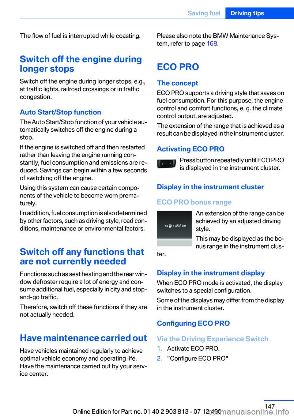
ECO PRO bonus range An extension of the range can be
achieved by an adjusted driving
style.
This may be displayed as the bo‐
nus range in the instrument clus‐
ter.
Display in the instrument display
When ECO PRO mode is activated, the display
switches to a special configuration.
Some of the displays may differ from the display
in the instrument cluster.
Configuring ECO PRO
Via the Driving Experience Switch1.Activate ECO PRO.2."Configure ECO PRO"Seite 147Saving fuelDriving tips147
Online Edition for Part no. 01 40 2 903 813 - 07 12 490