2013 BMW X1 XDRIVE 35I tailgate
[x] Cancel search: tailgatePage 38 of 291

To switch the engine off with transmission po‐
sition N engaged, insert the remote control in
the ignition lock.
Malfunction
The Comfort Access functions can be disturbed
by local radio waves, such as by a mobile phone
in the immediate vicinity of the remote control or
when a mobile phone is being charged in the
vehicle.
If this occurs, open or close the vehicle using the
buttons on the remote control or use the
integrated key in the door lock.
To start the engine afterward, insert the remote
control into the ignition switch.
Warning lamps The warning lamp in the instrument
cluster lights up when you attempt to
start the engine: the engine cannot be
started.
The remote control is not in the vehicle or has a
malfunction. Take the remote control with you
inside the vehicle or have it checked. If neces‐
sary, insert another remote control into the ig‐
nition switch.
The warning lamp in the instrument
cluster lights up while the engine is
running: the remote control is no lon‐
ger inside the vehicle.
After switching off the engine, the engine can
only be started again within approx. 10 seconds
if no door has been opened.
The indicator lamp in the instrument
cluster comes on and a message ap‐
pears on the Control Display: replace
the remote control battery.Replacing the battery
The remote control for Comfort Access con‐
tains a battery that will need to be replaced from
time to time.1.Take the integrated key out of the remote
control, refer to page 30.2.Remove the cover.3.Insert a new battery of the same type with
the positive side facing upwards.4.Press the cover closed.
Return used battery to a recycling collec‐
tion point or to your service center.
Alarm system
The concept
The vehicle alarm system responds to:
▷Opening of a door, the hood or the tailgate.▷Movements in the vehicle: interior motion
sensor, refer to page 39.▷Changes in the vehicle tilt, e.g., during at‐
tempts to steal a wheel or tow the car.▷Interruptions in battery voltage.
The alarm system briefly indicates tampering:
▷By sounding an acoustic alarm.▷By switching on the hazard warning system.▷By flashing the high beams.Seite 38ControlsOpening and closing38
Online Edition for Part no. 01 40 2 914 595 - VI/12
Page 39 of 291

Arming and disarming the alarm
system
General information
When you lock or unlock the vehicle, either with
the remote control or at the door lock, the alarm
system is armed or disarmed at the same time.
Door lock and armed alarm system
Unlocking via the door lock will trigger the alarm
on some market-specific versions.
To stop this alarm, unlock the vehicle with the
remote control or switch on the ignition.
Tailgate and armed alarm system
The tailgate can be opened using the remote
control, even if the alarm system is armed.
Press the button on the remote control.
After the tailgate is closed, it is locked and moni‐
tored again by the alarm system. The hazard
warning system flashes once.
In some market-specific versions, the tailgate
can only be opened using the remote control if
the vehicle was unlocked first.
Switching off the alarm
▷Unlock the vehicle using the remote control,
refer to page 32.▷Insert the remote control all the way into the
ignition lock.
Indicator lamp on the interior rearview
mirror
▷The indicator lamp flashes briefly every
2 seconds:
The system is armed.▷The indicator lamp flashes after locking:
The doors, hood or tailgate is not closed
properly, but the rest of the vehicle is se‐
cured.
The indicator lamp flashes continuously af‐
ter approx. 10 seconds. The interior motion
sensor is not active.▷The indicator lamp goes out after unlocking:
The vehicle has not been tampered with.▷If the indicator lamp flashes after unlocking
until the remote control is inserted in the ig‐
nition, but for no longer than approx. 5 mi‐
nutes:
An alarm has been triggered.
Panic mode
In dangerous situations, trigger the alarm sys‐
tem:
Press the button on the remote control for at
least 3 seconds.
To switch off the alarm: press any button.
Tilt alarm sensor
The tilt of the vehicle is monitored.
The alarm system responds in situations such
as attempts to steal a wheel or tow the car.
Interior motion sensor
For the sensor to function properly, the windows
and panoramic glass sunroof must be closed.
Avoiding unintentional alarms
The tilt alarm sensor and interior motion sensor
can be switched off together, such as in the fol‐
lowing situations:
▷In duplex garages.▷During transport on car-carrying trains, at
sea or on a trailer.Seite 39Opening and closingControls39
Online Edition for Part no. 01 40 2 914 595 - VI/12
Page 102 of 291
Malfunction
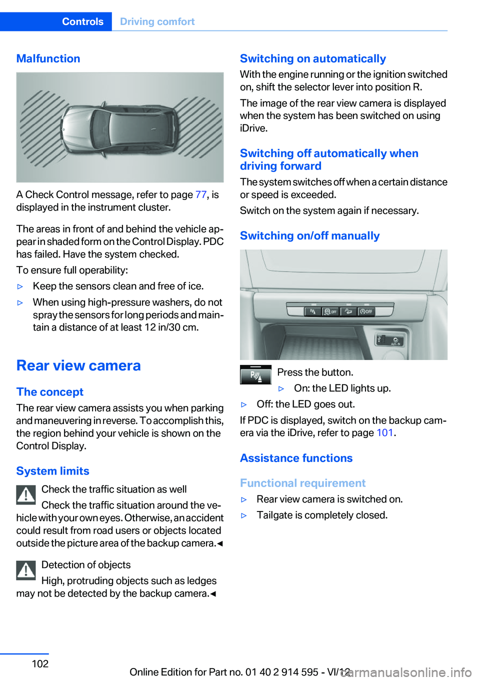
A Check Control message, refer to page 77, is
displayed in the instrument cluster.
The areas in front of and behind the vehicle ap‐
pear in shaded form on the Control Display. PDC
has failed. Have the system checked.
To ensure full operability:
▷Keep the sensors clean and free of ice.▷When using high-pressure washers, do not
spray the sensors for long periods and main‐
tain a distance of at least 12 in/30 cm.
Rear view camera
The concept
The rear view camera assists you when parking
and maneuvering in reverse. To accomplish this,
the region behind your vehicle is shown on the
Control Display.
System limits Check the traffic situation as well
Check the traffic situation around the ve‐
hicle with your own eyes. Otherwise, an accident
could result from road users or objects located
outside the picture area of the backup camera. ◀
Detection of objects
High, protruding objects such as ledges
may not be detected by the backup camera.◀
Switching on automatically
With the engine running or the ignition switched
on, shift the selector lever into position R.
The image of the rear view camera is displayed
when the system has been switched on using
iDrive.
Switching off automatically when
driving forward
The system switches off when a certain distance
or speed is exceeded.
Switch on the system again if necessary.
Switching on/off manually
Press the button.
▷On: the LED lights up.▷Off: the LED goes out.
If PDC is displayed, switch on the backup cam‐
era via the iDrive, refer to page 101.
Assistance functions
Functional requirement
▷Rear view camera is switched on.▷Tailgate is completely closed.Seite 102ControlsDriving comfort102
Online Edition for Part no. 01 40 2 914 595 - VI/12
Page 104 of 291
Show the obstacle marking via the iDrive, refer
to page 104.
Activating assistance functions
Several assistance functions can be active at the
same time.
Showing the parking aid lines
"Parking aid lines"
Pathway and turning lines are displayed.
Showing the obstacle marking
"Obstacle marking"
Three-dimensionally-shaped markings are dis‐
played.
Image on the Control Display
Switching on the rear view camera
using iDrive
With PDC activated:
"Rear view camera"
The image of the rear view camera is displayed.
The setting is stored for the remote control cur‐
rently in use.
Brightness
With the rear view camera switched on:
1. Select the symbol.2.Turn the controller until the desired setting
is reached and press the controller.
Contrast
With the rear view camera switched on:
1. Select the symbol.2.Turn the controller until the desired setting
is reached and press the controller.Camera
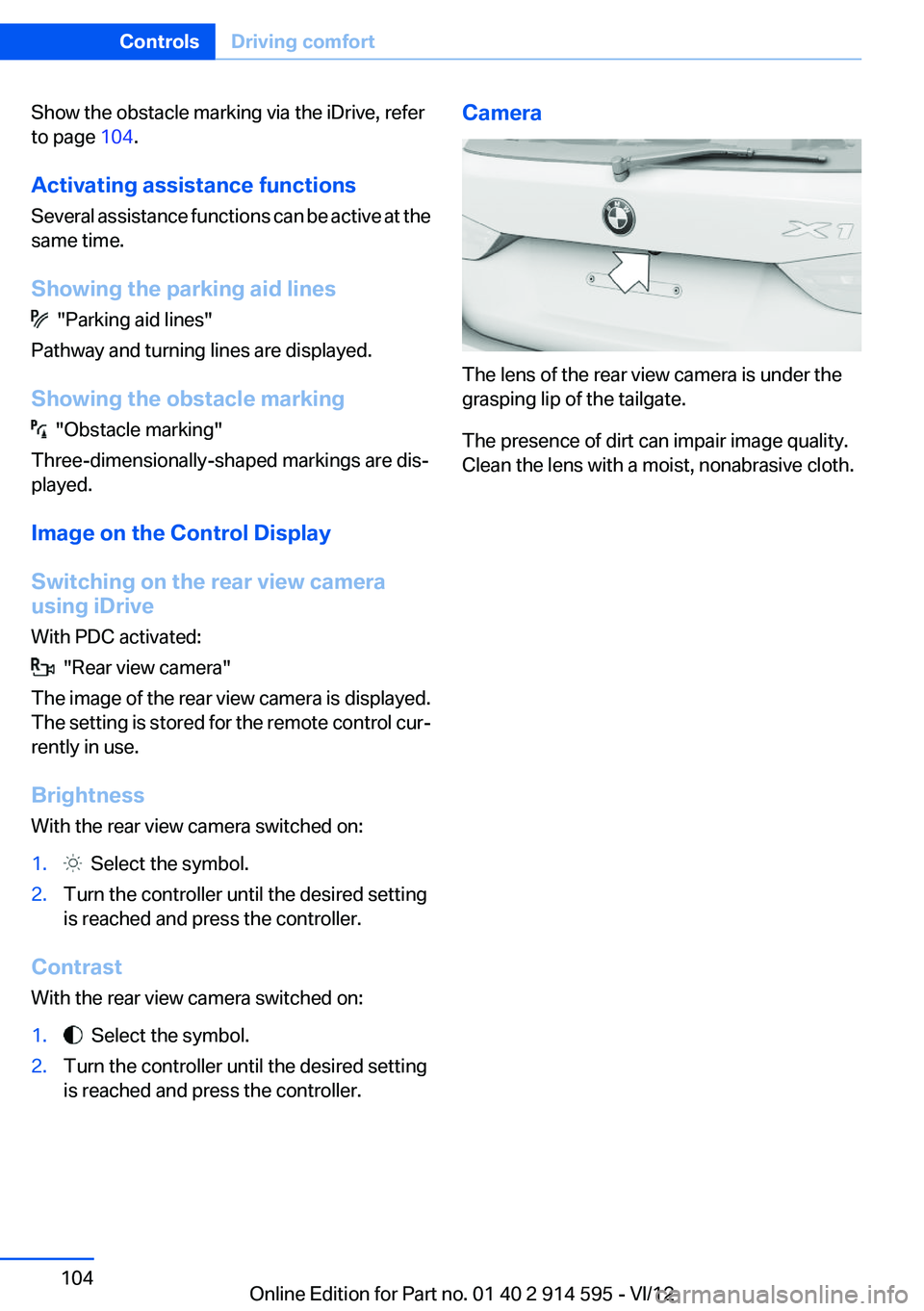
The lens of the rear view camera is under the
grasping lip of the tailgate.
The presence of dirt can impair image quality.
Clean the lens with a moist, nonabrasive cloth.
Seite 104ControlsDriving comfort104
Online Edition for Part no. 01 40 2 914 595 - VI/12
Page 115 of 291
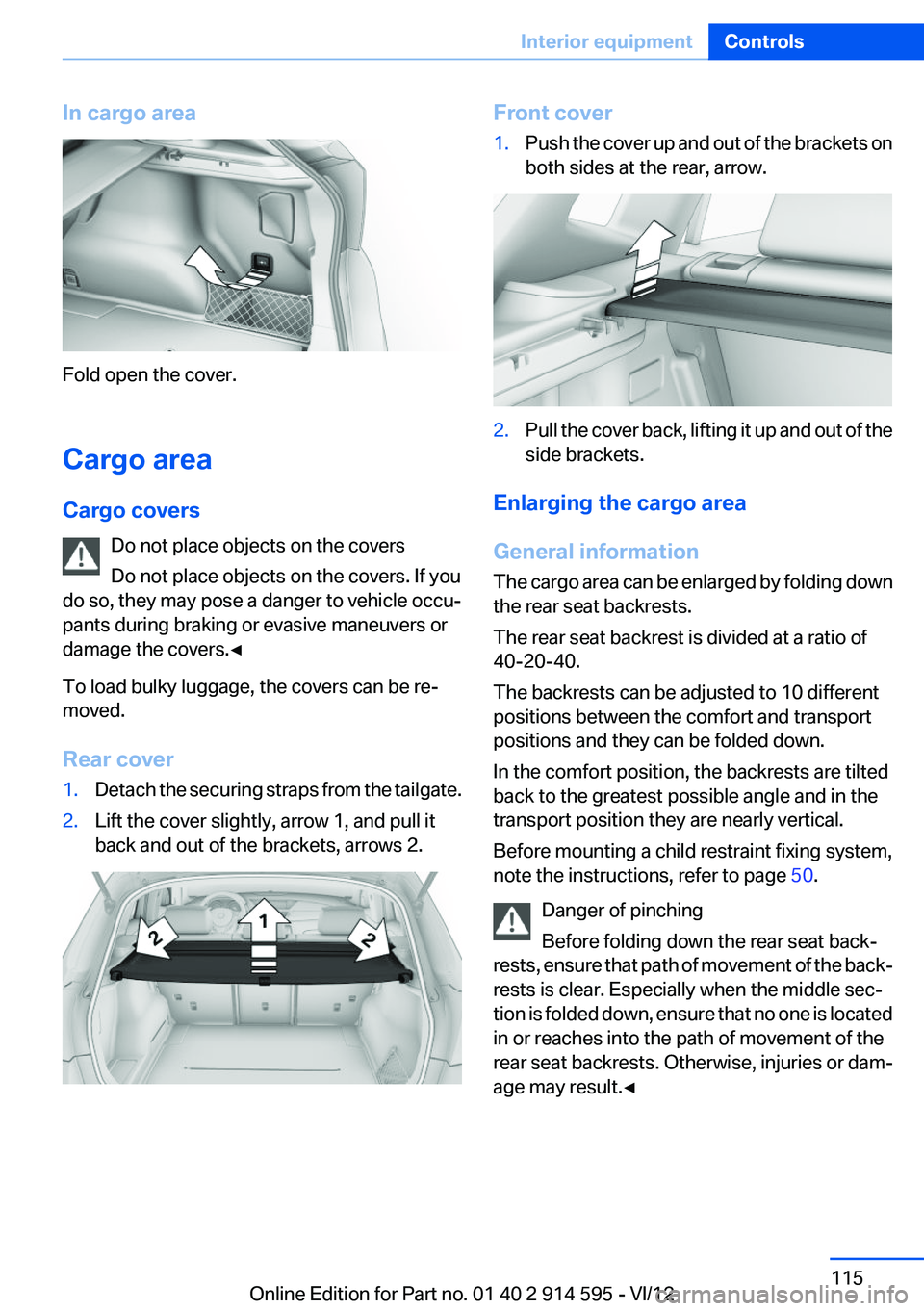
In cargo area
Fold open the cover.
Cargo area
Cargo covers Do not place objects on the covers
Do not place objects on the covers. If you
do so, they may pose a danger to vehicle occu‐
pants during braking or evasive maneuvers or
damage the covers.◀
To load bulky luggage, the covers can be re‐
moved.
Rear cover
1.Detach the securing straps from the tailgate.2.Lift the cover slightly, arrow 1, and pull it
back and out of the brackets, arrows 2.Front cover1.Push the cover up and out of the brackets on
both sides at the rear, arrow.2.Pull the cover back, lifting it up and out of the
side brackets.
Enlarging the cargo area
General information
The cargo area can be enlarged by folding down
the rear seat backrests.
The rear seat backrest is divided at a ratio of
40-20-40.
The backrests can be adjusted to 10 different
positions between the comfort and transport
positions and they can be folded down.
In the comfort position, the backrests are tilted
back to the greatest possible angle and in the
transport position they are nearly vertical.
Before mounting a child restraint fixing system,
note the instructions, refer to page 50.
Danger of pinching
Before folding down the rear seat back‐
rests, ensure that path of movement of the back‐
rests is clear. Especially when the middle sec‐
tion is folded down, ensure that no one is located
in or reaches into the path of movement of the
rear seat backrests. Otherwise, injuries or dam‐
age may result.◀
Seite 115Interior equipmentControls115
Online Edition for Part no. 01 40 2 914 595 - VI/12
Page 118 of 291
Removing
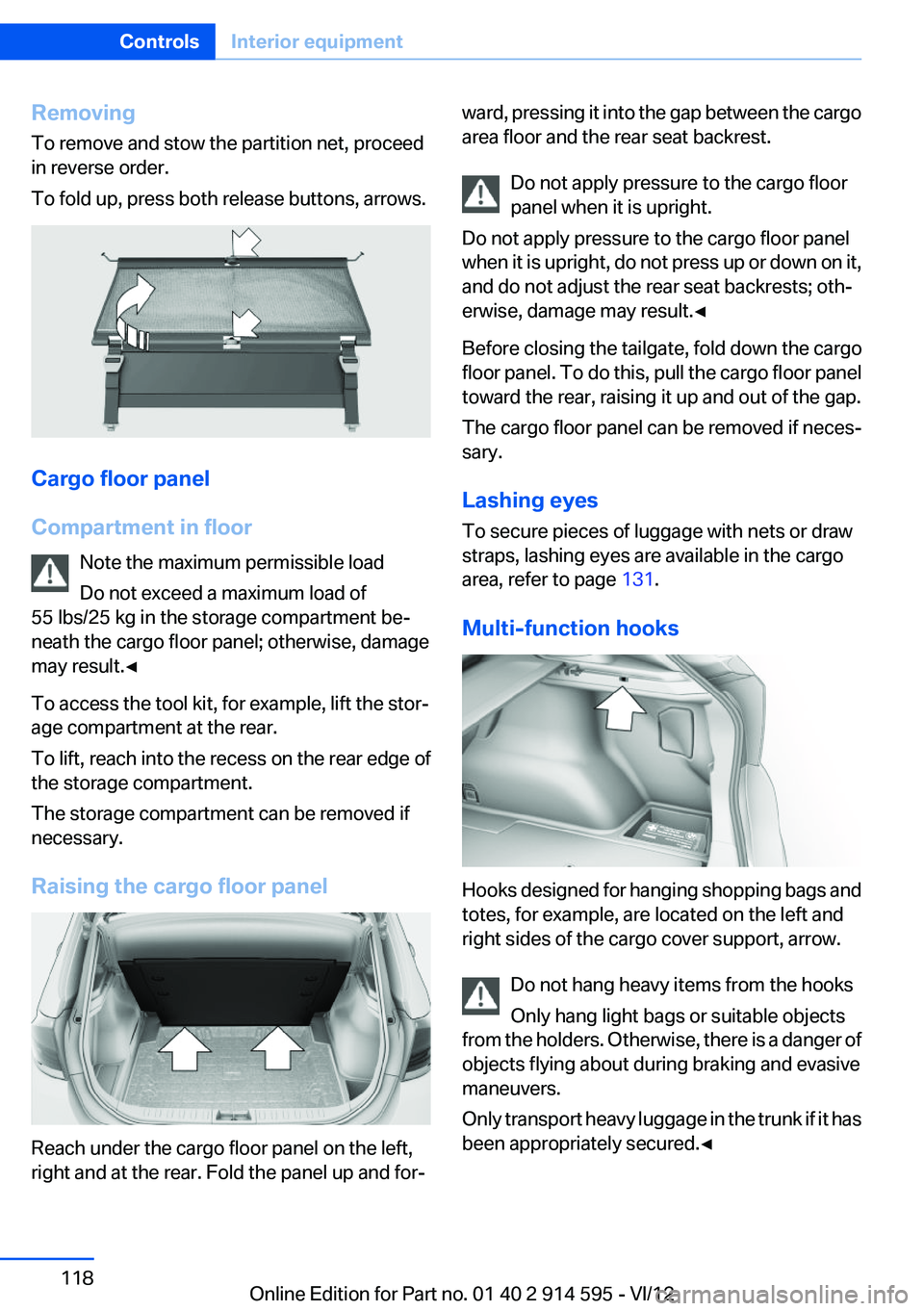
To remove and stow the partition net, proceed
in reverse order.
To fold up, press both release buttons, arrows.
Cargo floor panel
Compartment in floor Note the maximum permissible load
Do not exceed a maximum load of
55 lbs/25 kg in the storage compartment be‐
neath the cargo floor panel; otherwise, damage
may result.◀
To access the tool kit, for example, lift the stor‐
age compartment at the rear.
To lift, reach into the recess on the rear edge of
the storage compartment.
The storage compartment can be removed if
necessary.
Raising the cargo floor panel
Reach under the cargo floor panel on the left,
right and at the rear. Fold the panel up and for‐
ward, pressing it into the gap between the cargo
area floor and the rear seat backrest.
Do not apply pressure to the cargo floor
panel when it is upright.
Do not apply pressure to the cargo floor panel
when it is upright, do not press up or down on it,
and do not adjust the rear seat backrests; oth‐
erwise, damage may result.◀
Before closing the tailgate, fold down the cargo
floor panel. To do this, pull the cargo floor panel
toward the rear, raising it up and out of the gap.
The cargo floor panel can be removed if neces‐
sary.
Lashing eyes
To secure pieces of luggage with nets or draw
straps, lashing eyes are available in the cargo
area, refer to page 131.
Multi-function hooks
Hooks designed for hanging shopping bags and
totes, for example, are located on the left and
right sides of the cargo cover support, arrow.
Do not hang heavy items from the hooks
Only hang light bags or suitable objects
from the holders. Otherwise, there is a danger of
objects flying about during braking and evasive
maneuvers.
Only transport heavy luggage in the trunk if it has
been appropriately secured.◀
Seite 118ControlsInterior equipment118
Online Edition for Part no. 01 40 2 914 595 - VI/12
Page 126 of 291
Things to remember when drivingVehicle equipment
This chapter describes all series equipment as
well as country-specific and special equipment
offered for this model series.Therefore, it also
describes equipment that may not be found in
your vehicle, for instance due to the selected
special equipment or the country version. This
also applies to safety-related functions and sys‐
tems.
Breaking-in period
General information
Moving parts need to be broken in to adjust to
each other.
The following instructions will help achieve a
long vehicle life and good economy.
Engine and differential
Always obey all official speed limits.
Up to 1,200 miles/2,000 km
Do not exceed the maximum engine and road
speeds:▷For a gasoline engine, 4,500 rpm and
100 mph/160 km/h.
Avoid full-throttle operation and use of the
transmission's kickdown mode for the initial
miles.
From 1,200 miles/2,000 km
The engine and vehicle speed can gradually be
increased.
Tires
Due to technical factors associated with their
manufacture, tires do not achieve their full trac‐
tion potential until after an initial breaking-in pe‐
riod.
Drive conservatively for the first
200 miles/300 km.
Brake system
Brakes require an initial break-in period of ap‐
prox. 300 miles/500 km to achieve optimized
contact and wear patterns between brake pads
and rotors. Drive cautiously during this break-in
period.
Following part replacement
The same breaking in procedures should be ob‐
served if any of the components mentioned
above have to be renewed in the course of the
vehicle's operating life.
General driving notes
Closing tailgate Drive with the tailgate closed
Only drive with the tailgate closed; other‐
wise, passengers and other road users may be
endangered or the vehicle may be damaged if an
accident occurs or during braking or evasive
maneuvers. In addition, exhaust fumes may en‐
ter the passenger compartment.◀
If, despite this, the vehicle must be driven with
the tailgate open:▷Drive moderately.▷Close all windows and the panoramic glass
sunroof.▷Greatly increase the blower speed.
Hot exhaust system
Hot exhaust system
High temperatures are generated in the
exhaust system.
Seite 126Driving tipsThings to remember when driving126
Online Edition for Part no. 01 40 2 914 595 - VI/12
Page 132 of 291
Roof-mounted luggage rack
Notes
A special rack system is available as an optional
accessory.
Anchorage points
The anchorage points are located on the roof
railing.
Attachment
Follow the installation instructions for the roof-
mounted luggage rack.
Be sure that adequate clearance is maintained
for tilting and opening the panoramic glass sun‐
roof.
Loading
Because roof racks raise the vehicle's center of
gravity when loaded, they have a major effect on
vehicle handling and steering response.
Therefore, note the following when loading and
driving:▷Do not exceed the approved roof/axle loads
and the approved gross vehicle weight.▷Distribute the roof load uniformly.▷The roof load should not be too large in area.▷Always load the heaviest pieces on the bot‐
tom.▷Fasten the roof-mounted luggage securely,
for instance using lashing straps.▷Do not let objects project into the opening
path of the tailgate.▷Drive smoothly. Avoid sudden acceleration
and braking maneuvers. Take corners gen‐
tly.Rear luggage rack
Notes
A special rear rack is available as an optional ac‐
cessory. It does not require a trailer hitch.
Follow the installation instructions for the rear
rack.
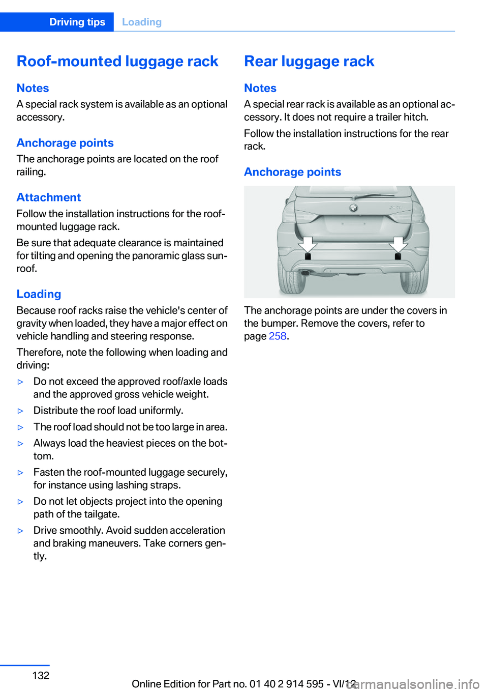
Anchorage points
The anchorage points are under the covers in
the bumper. Remove the covers, refer to
page 258.
Seite 132Driving tipsLoading132
Online Edition for Part no. 01 40 2 914 595 - VI/12