2013 BMW X1 XDRIVE 28I mirror controls
[x] Cancel search: mirror controlsPage 83 of 291

▷High beams off/headlamp flasher, arrow 2.
To reactivate the High-beam Assistant, briefly
push the turn indicator lever toward the high
beams.
Activating/deactivating via iDrive
1."Settings"2."Lighting"3."High beam assistant"
The setting is stored for the remote control cur‐
rently in use.
System limits Personal responsibility
The High-beam Assistant cannot serve as
a substitute for the driver's personal judgment
of when to use the high beams. Therefore, man‐
ually switch off the high beams in situations
where this is required to avoid a safety risk.◀
The system is not fully functional in situations
such as the following, and driver intervention
may be necessary:
▷In very unfavorable weather conditions,
such as fog or heavy precipitation.▷In detecting poorly-lit road users, such as
pedestrians, cyclists, horseback riders and
wagons; when driving close to train or ship
traffic; and at animal crossings.▷In tight curves, on hilltops or in depressions,
in cross traffic or half-obscured oncoming
traffic on freeways.▷In poorly-lit towns and cities and in the pres‐
ence of highly reflective signs.▷At low speeds.▷When the windshield in front of the interior
rearview mirror is fogged over, dirty or cov‐
ered with stickers, etc.▷If the sensor view field is dirty.
The view field of the sensor is located on the
front of the interior rearview mirror.
Do not cover this area with stickers, etc.
Clean the sensor view field with a cloth mois‐
tened with a small amount of glass cleaner.
Fog lamps
Front fog lamps
The parking lamps or low beams must be
switched on.
Press the button. The green indicator
lamp in the instrument cluster lights up.
If the automatic headlamp control, refer to
page 81, is activated, the low beams will come
on automatically when you switch on the fog
lamps.
Instrument lighting
The parking lamps or low beams must be
switched on to adjust the brightness.
1.Push button 1 up or down repeatedly until
the appropriate symbol appears in the dis‐Seite 83LampsControls83
Online Edition for Part no. 01 40 2 914 595 - VI/12
Page 86 of 291

Protective action
Airbags are not triggered in every impact situa‐
tion, e.g., in less severe accidents or rear-end
collisions.
Information on how to ensure the optimal
protective effect of the airbags▷Keep at a distance from the airbags.▷Always grasp the steering wheel on the
steering wheel rim, holding your hands at
the 3 o'clock and 9 o'clock positions, to keep
the danger of injury to your hands or arms as
low as possible if the airbag is triggered.▷There should be no people, animals, or ob‐
jects between an airbag and a person.▷Do not use the cover of the front airbag on
the front passenger side as a storage area.▷Keep the dashboard and window on the
front passenger side clear, i.e., do not cover
with adhesive labels or coverings, and do not
attach holders such as for navigation instru‐
ments and mobile phones.▷Make sure that the front passenger is sitting
correctly, i.e., keeps his or her feet and legs
in the footwell; otherwise, leg injuries can
occur if the front airbag is triggered.▷Do not place slip covers, seat cushions or
other objects on the front passenger seat
that are not approved specifically for seats
with integrated side airbags.▷Do not hang pieces of clothing, such as jack‐
ets, over the backrests.▷Make sure that occupants keep their heads
away from the side airbag and do not rest
against the head airbag; otherwise, injuries
can occur if the airbags are triggered.▷Do not remove the airbag restraint system.▷Do not remove the steering wheel.▷Do not apply adhesive materials to the air‐
bag cover panels, cover them or modify
them in any way.▷Never modify either the individual compo‐
nents or the wiring in the airbag system. This
also applies to steering wheel covers, the
dashboard, the seats, the roof pillars and the
sides of the headliner.◀
Even when all instructions are followed closely,
injury from contact with the airbags cannot be
ruled out in certain situations.
The ignition and inflation noise may lead to
short-term and, in most cases, temporary hear‐
ing impairment in sensitive individuals.
In the case of a malfunction, deactivation
and after triggering of the airbags
Do not touch the individual components imme‐
diately after the system has been triggered; oth‐
erwise, there is the danger of burns.
Only have the airbags checked, repaired or dis‐
mantled and the airbag generator scrapped by
your service center or a workshop that has the
necessary authorization for handling explosives.
Non-professional attempts to service the sys‐
tem could lead to failure in an emergency or un‐
desired triggering of the airbag, either of which
could result in injury.◀
Warnings and information on the airbags are
also found on the sun visors.
Automatic deactivation of the front
passenger airbags
The system determines whether the front pas‐
senger seat is occupied by measuring the re‐
sistance of the human body.
The front and side airbags on the front passen‐
ger side are activated or deactivated accordingly
by the system.
The indicator lamp above the interior rearview
mirror shows the current status of the front pas‐
senger airbags, deactivated or activated, refer to
Front passenger airbag indicator lamp below.
Seite 86ControlsSafety86
Online Edition for Part no. 01 40 2 914 595 - VI/12
Page 110 of 291

Interior equipmentVehicle equipment
This chapter describes all series equipment as
well as country-specific and special equipment
offered for this model series.Therefore, it also
describes equipment that may not be found in
your vehicle, for instance due to the selected
special equipment or the country version. This
also applies to safety-related functions and sys‐
tems.
Universal Garage Door
Opener
The concept
The Universal Garage Door Opener can be used
to operate up to 3 functions in remote-control‐
led systems, such as garage door drives or light‐
ing systems. The Universal Garage Door Opener
replaces up to 3 different hand-held transmit‐
ters. To operate it, the buttons on the interior
rearview mirror must be programmed for the de‐
sired functions. The hand-held transmitter for
the system is needed for the programming pro‐
cedure.
During programming
During programming and before activat‐
ing a device using the Universal Garage Door
Opener, ensure that there are no people, ani‐
mals, or objects in the range of movement of the
remote-controlled device; otherwise, there is a
risk of injury or damage.
Also follow the safety instructions of the hand-
held transmitter.◀
Before selling the vehicle, delete the stored
functions for security reasons.
Compatibility If this symbol is printed on the packaging
or in the operating instructions of thesystem being operated, the system is generally
compatible with the Universal Garage Door
Opener.
If you have any questions, please contact:▷Your service center.▷www.homelink.com on the Internet.
HomeLink is a registered trademark of Johnson
Controls, Inc.
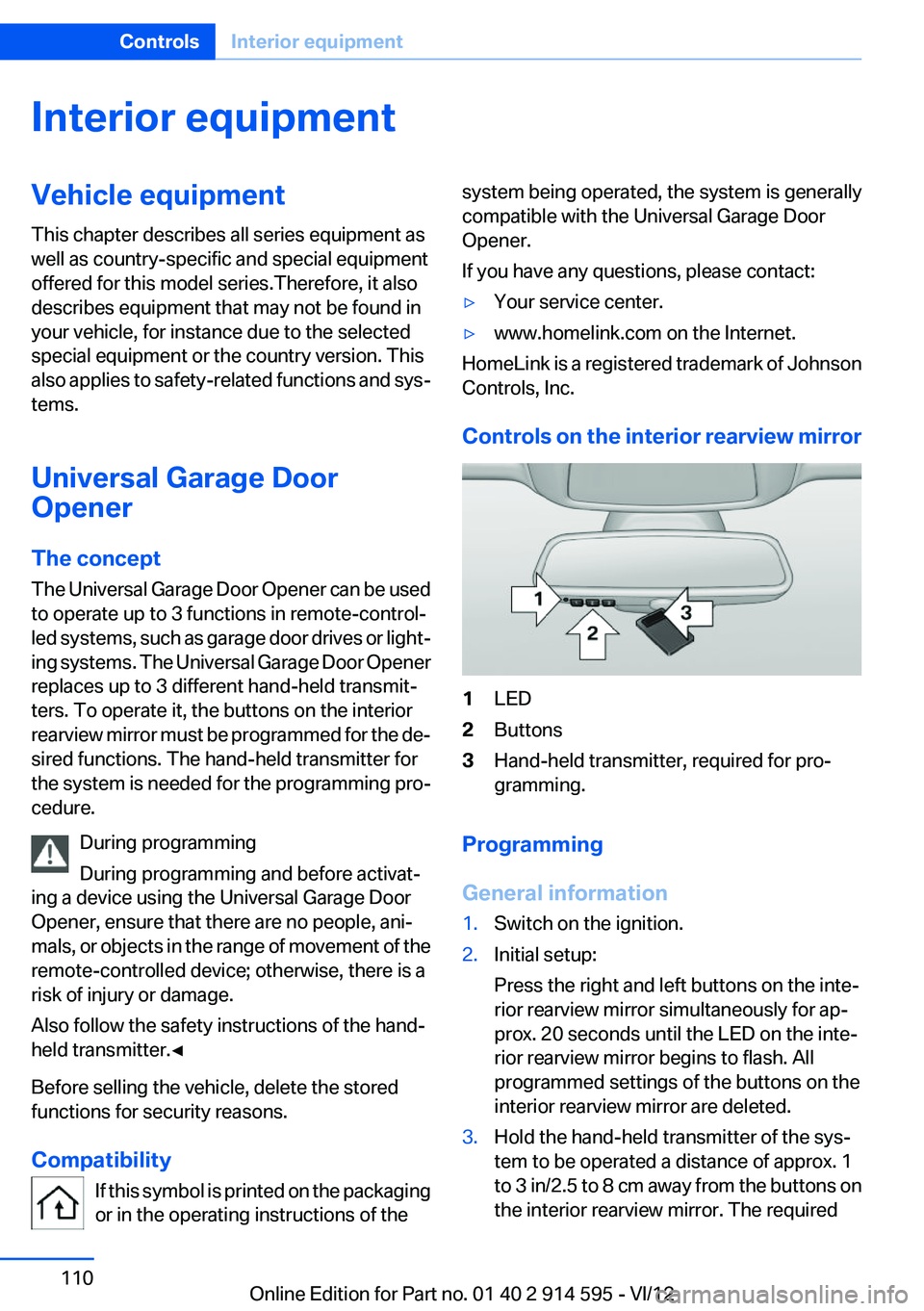
Controls on the interior rearview mirror
1LED2Buttons3Hand-held transmitter, required for pro‐
gramming.
Programming
General information
1.Switch on the ignition.2.Initial setup:
Press the right and left buttons on the inte‐
rior rearview mirror simultaneously for ap‐
prox. 20 seconds until the LED on the inte‐
rior rearview mirror begins to flash. All
programmed settings of the buttons on the
interior rearview mirror are deleted.3.Hold the hand-held transmitter of the sys‐
tem to be operated a distance of approx. 1
to 3 in/2.5 to 8 cm away from the buttons on
the interior rearview mirror. The requiredSeite 110ControlsInterior equipment110
Online Edition for Part no. 01 40 2 914 595 - VI/12
Page 111 of 291

distance depends on the particular hand-
held transmitter.4.Press the button of the desired function on
the hand-held transmitter and the button
being programmed on the interior rearview
mirror simultaneously and hold. The LED on
the interior rearview mirror flashes slowly at
first.5.When the LED flashes more rapidly, release
both buttons. Rapid flashing indicates that
the button on the interior rearview mirror has
been programmed.
If the LED does not flash faster after 60 sec‐
onds, change the distance between the in‐
terior rearview mirror and the hand-held
transmitter and repeat the step. Multiple tri‐
als at different distances may be necessary.
Wait at least 15 seconds between trials.6.To program additional functions on other
buttons, repeat steps 3 to 5.
The systems can be operated with the buttons
on the interior rearview mirror.
Special characteristics of alternating-
code radio systems
If the system cannot be operated after repeated
programming, check whether the system to be
operated uses an alternating-code system.
Read the operating instructions of the system or
press and hold the programmed button on the
interior rearview mirror. If the LED on the interior
rearview mirror flashes rapidly at first and then
lights up continuously for 2 seconds, the system
is equipped with an alternating-code system.
This flashing LED pattern repeats itself for ap‐
prox. 20 seconds.
In systems with an alternating-code system, the
Universal Garage Door Opener and the system
must be additionally synchronized.
Please obtain additional information on syn‐
chronization in the operating instructions of the
system being set up.
The systems will be easier to synchronize with
the aid of a second person.
Synchronization:1.Park the vehicle within range of the remote-
controlled system.2.Program the corresponding button on the
interior rearview mirror as described.3.Identify and press the synchronization but‐
ton on the system being set up. You have
approx. 30 seconds for the next step.4.Press and hold the button on the interior
rearview mirror for approx. 3 seconds and
then release it. Repeat this step up to three
times if necessary to complete the synchro‐
nization procedure. When synchronization
is completed, the programmed function is
executed.
Reprogramming individual buttons
1.Switch on the ignition.2.Hold the hand-held transmitter at a distance
of approx. 1 to 3 in/2.5 to 8 cm from the
memory buttons.
The required distance depends on the par‐
ticular hand-held transmitter.3.Press the memory button of the Universal
Garage Door Opener.4.If the LED flashes slowly after approx.
20 seconds, press the transmit button on
the hand-held transmitter.5.Release both buttons when the LED flashes
rapidly.
If the LED does not flash rapidly after approx.
60 seconds, change the distance and repeat
the step.
Canada: if the LED does not flash rapidly af‐
ter approx. 60 seconds, change the distance
and repeat the step. If programming was
aborted by the hand-held transmitter, hold
down the memory button and press and re‐
lease the button on the hand-held transmit‐
ter several times for 2 seconds.Seite 111Interior equipmentControls111
Online Edition for Part no. 01 40 2 914 595 - VI/12
Page 112 of 291

ControlsPrior to operation
Before operating a unit with the Universal
Garage Door Opener, ensure that there are no
people, animals, or objects in the range of move‐
ment of the system; otherwise, there is a risk of
injury or damage.
Also follow the safety instructions of the hand-
held transmitter.◀
The system, such as the garage door, can be
operated using the button on the interior rear‐
view mirror with the engine running or the igni‐
tion switched on. When you are within the re‐
ception range of the system, press and hold the
button until the function is initiated. The LED on
the interior rearview mirror lights up continu‐
ously while the radio signal is being transmitted.
Deleting stored functions
Press the right and left buttons on the interior
rearview mirror simultaneously for approx.
20 seconds until the LED flashes rapidly. All
stored functions are deleted. The functions can‐
not be deleted individually.
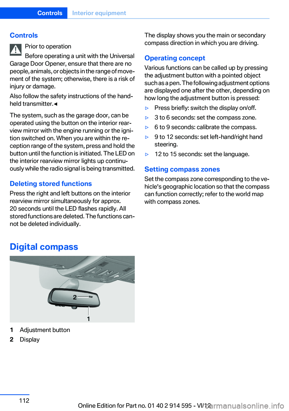
Digital compass1Adjustment button2DisplayThe display shows you the main or secondary
compass direction in which you are driving.
Operating concept
Various functions can be called up by pressing
the adjustment button with a pointed object
such as a pen. The following adjustment options
are displayed one after the other, depending on
how long the adjustment button is pressed:▷Press briefly: switch the display on/off.▷3 to 6 seconds: set the compass zone.▷6 to 9 seconds: calibrate the compass.▷9 to 12 seconds: set left-hand/right hand
steering.▷12 to 15 seconds: set the language.
Setting compass zones
Set the compass zone corresponding to the ve‐
hicle's geographic location so that the compass
can function correctly; refer to the world map
with compass zones.
Seite 112ControlsInterior equipment112
Online Edition for Part no. 01 40 2 914 595 - VI/12
Page 279 of 291

Cruise control 98
Cruise control– Malfunction 99
Cupholder 122
Curb weight, refer to Weights 267
Current fuel consumption 69
Current location, storing 142
Curve lights, refer to Adaptive light control 81
D
Dashboard lighting, refer to In‐ strument lighting 83
Dashboard, refer to Cock‐ pit 12
Data, technical 266
Date
– Date format 74– Setting 73
Daytime running lights 81
Daytime running lights, bulb replacement 248
Defroster
– Rear window 107
Destination entry via the ad‐
dress book 142
Destination guidance 149
Destination guidance with in‐ termediate destinations 147
Destination input, naviga‐ tion 140
Digital clock 68
Digital compass 112
Digital radio 163
Dimming mirrors 49
Directional indicators, refer to Turn signals 59
Display lighting, refer to Instru‐ ment lighting 83
Displays and controls 12
Displays, care 262
Displays, cleaning 262
Displays, refer to Instrument cluster 14
Disposal, coolant 242
Disposal, vehicle battery 251
Distance warning, refer to Park Distance Control PDC 100
Divided rear seat backrest, re‐ fer to Enlarging the cargo
area 115
Divided screen view, split screen 22
Door key, refer to Remote con‐ trol with integrated key 30
Door lock 34
Doors, manual operation 34
Doors, unlocking and locking– Confirmation signals 33– From the inside 34– From the outside 32
DOT Quality Grades 233
Downhill control 96
Draft-free ventilation 108
Drive-off assistant 97
Driving away on inclines, refer to Drive-off assistant 97
Driving notes, breaking in 126
Driving notes, general 126
Driving on poor roads 128
Driving stability control sys‐ tems 94
Driving through water 127
Driving tips, refer to Driving notes 126
Dry air, refer to Cooling func‐ tion 107
DSC Dynamic Stability Con‐ trol 94
DTC Dynamic Traction Con‐ trol 95
DTMF suffix dialing 198
DVD/CD 170
DVDs, storing 176
DVD, video 172
Dynamic destination guid‐ ance 156
Dynamic Stability Control DSC 94
Dynamic Traction Control DTC 95
E
ECO PRO 134
ECO PRO display 134
ECO PRO driving mode 134
ECO PRO mode 134
EfficientDynamics, refer to Saving fuel 133
Electrical malfunction– Door lock 34– Driver's door 34– Fuel filler flap 225– Tailgate 36
Electric seat adjustment 44
Electronic brake-force distri‐ bution 94
Electronic engine oil level check 239
Electronic Stability Program ESP, refer to Dynamic Stabil‐
ity Control DSC 94
Emergency activation
– Automatic transmission, re‐
fer to Overriding selector
lever lock 64
Emergency operation
– Door lock, refer to Manual
operation 34
Emergency operation, fuel
filler flap, unlocking man‐
ually 225
Emergency Request 253
Emergency service, refer to Roadside Assistance 254
Energy-conscious driving, re‐ fer to Current fuel consump‐
tion 69
Energy, saving
– Automatic Engine Start/Stop
Function 56
Energy, saving, refer to Saving
fuel 133
Engine, breaking in 126
Engine compartment 238
Engine coolant, refer to Cool‐ ant 242
Engine oil, adding 241
Seite 279Everything from A to ZReference279
Online Edition for Part no. 01 40 2 914 595 - VI/12