2013 BMW X1 XDRIVE 28I ECO mode
[x] Cancel search: ECO modePage 69 of 291

Tachometer
Never force the engine speed up into the red
warning field, see arrow. In this range, the fuel
supply is interrupted to protect the engine.
Coolant temperature
A warning lamp will come on if the coolant, and
therefore the engine, becomes too hot. In addi‐
tion, a message will appear on the Control Dis‐
play.
Check the coolant level, refer to page 242.
Current fuel consumption
Displays the current fuel consumption. You can
check whether you are currently driving in an ef‐
ficient and environmentally-friendly manner.
Engine oil temperature▷Cold engine: the pointer is at the low tem‐
perature end. Drive at moderate engine and
vehicle speeds.▷Normal operating temperature: the pointer
is in the middle or in the right half of the tem‐
perature display.▷Hot engine: the pointer is at the high tem‐
perature end. Switch off the engine imme‐
diately and allow it to cool down.
If the engine oil temperature is too high, a mes‐
sage appears on the Control Display.
Check the oil level, refer to page 239.
Fuel gauge
The vehicle inclination may cause the display to
vary.
The arrow on the fuel pump symbol indicates
the side of the vehicle with the fuel filler flap.
Notes on refueling, refer to page 224.
Range
After the reserve range is reached:
Seite 69DisplaysControls69
Online Edition for Part no. 01 40 2 914 595 - VI/12
Page 80 of 291

LampsVehicle equipment
This chapter describes all series equipment as
well as country-specific and special equipment
offered for this model series.Therefore, it also
describes equipment that may not be found in
your vehicle, for instance due to the selected
special equipment or the country version. This
also applies to safety-related functions and sys‐
tems.
At a glance1Automatic headlamp control / adaptive light
control / high-beam Assistant / welcome
lamps / daytime running lights2Lamps off / daytime running lights3Parking lamps / daytime running lights4Low beams/welcome lamps5Fog lamps
Parking lamps/low beams,
headlamp control
General information
If the driver's door is opened while the ignition is
switched off, the exterior lighting is switched off
automatically in the following switch settings:
0,
,
Parking lamps
Switch position
: the vehicle lamps light
up on all sides, e.g., for parking.
Do not use the parking lamps for extended pe‐
riods; otherwise, the battery may become dis‐
charged and it would then be impossible to start
the engine.
When parking, it is preferable to switch on the
one-sided roadside parking lamps, refer to
page 82.
Low beams
Switch position
with the ignition switched
on: the low beams light up.
Welcome lamps
When parking the vehicle, leave the switch in
position
or : the parking and interior
lamps light up briefly when the vehicle is un‐
locked.
Activating/deactivating the welcome
lamps
1."Settings"2."Lighting"3."Welcome light"
The setting is stored for the remote control cur‐
rently in use.
Seite 80ControlsLamps80
Online Edition for Part no. 01 40 2 914 595 - VI/12
Page 92 of 291

Because the possible driving distance depends
on how the vehicle is used during the trip, the
actual distance may be smaller or greater de‐
pending on the driving speed, road conditions,
external temperature, cargo load, etc.
Continued driving with a flat tire
Drive moderately and do not exceed a
speed of 50 mph/80 km/h.
A loss of tire inflation pressure results in a
change in the handling characteristics, e.g., re‐
duced lane stability during braking, a longer
braking distance and altered self-steering prop‐
erties.◀
Final tire failure
Vibrations or loud noises while driving can
indicate the final failure of the tire. Reduce speed
and stop; otherwise, pieces of the tire could
come loose and cause an accident. Do not con‐
tinue driving, and contact your service center. ◀
Message when the system was not
reset
The yellow warning lamp lights up. A
message appears on the Control Dis‐
play.
The system detected a wheel change but was
not reset.
Warnings regarding the current tire inflation
pressure are not reliable.
Check the tire inflation pressure and reset the
system.
Malfunction The small warning lamp flashes in yel‐
low and then lights up continuously;
the larger warning lamp comes on in
yellow. On the Control Display, the
tires are shown in gray and a message appears.
No flat tire can be detected.
Display in the following situations:▷A wheel without TPM electronics is fitted:
have the service center check it if necessary.▷Malfunction: have the system checked by
your service center.▷TPM could not be fully reset. Reset the sys‐
tem again.
The small warning lamp flashes in yel‐
low and then lights up continuously;
the larger warning lamp comes on in
yellow. On the Control Display, the
tires are shown in gray and a message appears.
No flat tire can be detected.
Display in the following situations:
▷Disturbance by systems or devices with the
same radio frequency: after leaving the area
of the disturbance, the system automatically
becomes active again.
Declaration according to NHTSA/
FMVSS 138 Tire Pressure Monitoring
Systems
Each tire, including the spare (if provided)
should be checked monthly when cold and in‐
flated to the inflation pressure recommended by
the vehicle manufacturer on the vehicle placard
or tire inflation pressure label (If your vehicle has
tires of a different size than the size indicated on
the vehicle placard or tire inflation pressure la‐
bel, you should determine the proper tire infla‐
tion pressure for those tires.).
As an added safety feature, your vehicle has
been equipped with a tire pressure monitoring
system (TPMS) that illuminates a low tire pres‐
sure telltale when one or more of your tires is
significantly under-inflated. Accordingly, when
the low tire pressure telltale illuminates, you
should stop and check your tires as soon as
possible, and inflate them to the proper pres‐
sure. Driving on a significantly under-inflated tire
causes the tire to overheat and can lead to tire
failure. Under-inflation also reduces fuel effi‐
ciency and tire tread life, and may affect the ve‐
hicle's handling and stopping ability.
Seite 92ControlsSafety92
Online Edition for Part no. 01 40 2 914 595 - VI/12
Page 94 of 291

Driving stability control systemsVehicle equipment
This chapter describes all series equipment as
well as country-specific and special equipment
offered for this model series.Therefore, it also
describes equipment that may not be found in
your vehicle, for instance due to the selected
special equipment or the country version. This
also applies to safety-related functions and sys‐
tems.
Antilock Brake System ABS
ABS prevents locking of the wheels during brak‐
ing.
The vehicle remains steerable even during full
brake applications, thus increasing active
safety.
ABS is operational every time you start the en‐
gine.
Electronic brake-force
distribution
The system controls the brake pressure in the
rear wheels to ensure stable braking behavior.
Brake assistant
When you apply the brakes rapidly, this system
automatically produces the maximum braking
force boost. It thus helps to achieve the shortest
possible braking distance during full braking.
This system utilizes all of the benefits provided
by ABS.
Do not reduce the pressure on the brake pedal
for the duration of the full braking.Dynamic Stability Control
DSC
The concept
DSC prevents traction loss in the driving wheels
when driving away and accelerating.
DSC also recognizes unstable vehicle condi‐
tions, such as fishtailing or nose-diving. Subject
to physical limits, DSC helps to keep the vehicle
on a steady course by reducing engine speed
and by applying brakes to the individual wheels.
Adjust your driving style to the situation
An appropriate driving style is always the
responsibility of the driver.
The laws of physics cannot be repealed, even
with DSC.
Do not reduce the additional safety margin with
a risky driving style, as otherwise there is a risk
of an accident.◀
Deactivating DSC: DSC OFF
When DSC is deactivated, driving stability is re‐
duced during acceleration and when driving in
bends.
To increase vehicle stability, activate DSC again
as soon as possible.
Deactivating DSC
Press and hold the button, but not lon‐
ger than approx. 10 seconds, until the
Seite 94ControlsDriving stability control systems94
Online Edition for Part no. 01 40 2 914 595 - VI/12
Page 105 of 291

ClimateVehicle equipment
This chapter describes all series equipment as
well as country-specific and special equipment
offered for this model series.Therefore, it alsodescribes equipment that may not be found in
your vehicle, for instance due to the selected
special equipment or the country version. This
also applies to safety-related functions and sys‐
tems.
Automatic climate control
1Manual air distribution2Maximum cooling3Temperature, left4AUTO program5Manual air flow rate, AUTO intensity6Display7Automatic recirculated air control/recircu‐
lated air mode8ALL program9Temperature, right10Defrosting windows and removing conden‐
sation11Switching cooling function on/off manually12Rear window defroster13Seat heating, right 4514Interior temperature sensor, please keep
clear15Seat heating, left 45Seite 105ClimateControls105
Online Edition for Part no. 01 40 2 914 595 - VI/12
Page 107 of 291

Press the left or right side of the button:
decrease or increase air volume.
The selected air volume is shown on the display
of the automatic climate control.
The air volume of the automatic climate control
may be reduced automatically to save battery
power.
Automatic recirculated air mode/
recirculated air mode
You can respond to unpleasant odors or pollu‐
tants in the immediate environment by tempo‐
rarily suspending the supply of outside air. The
system then recirculates the air currently within
the vehicle.
Press the button repeatedly to select
an operating mode:▷LEDs off: outside air flows in continuously.▷Left LED on, automatic recirculated-air con‐
trol: a sensor detects pollutants in the out‐
side air and controls the shutoff automati‐
cally.▷Right LED on, recirculated air mode: the
supply of outside air into the vehicle is per‐
manently blocked.
If the windows are fogged over, switch off
the recirculated-air mode and press the
AUTO button to utilize the condensation
sensor. Make sure that air can flow onto the
windshield.
Continuous recirculated-air mode
The recirculated air mode should not be
used for an extended period of time, as the air
quality inside the vehicle deteriorates steadily. ◀
Via the button on the steering wheel
A button on the steering wheel can be used to
quickly switch between recirculated air mode
and the previous setting.
ALL program
Press the button.
The current temperature setting for the
driver's side is transferred to the front passenger
side.
If the temperature setting is changed on the
driver's side, the temperature on the front pas‐
senger side changes as well.
The program is switched off if the setting is
changed on the front passenger side or the but‐
ton is pressed again.
Defrosting and defogging windows Press the button.
Ice and condensation are quickly re‐
moved from the windshield and the front side
windows.
For this purpose, also switch on the cooling
function.
Cooling function
The passenger compartment can only be
cooled with the engine running.
Press the button.
The air is cooled and dehumidified and
– depending on the temperature setting –
warmed again.
Depending on the weather, the windshield may
fog up briefly when the engine is started.
The cooling function is switched on automati‐
cally with the AUTO program.
When using the automatic climate control, con‐
densation water, refer to page 128, develops
that exits underneath the vehicle.
Rear window defroster Press the button.
The rear window defroster switches off
automatically after a certain period of time.Seite 107ClimateControls107
Online Edition for Part no. 01 40 2 914 595 - VI/12
Page 110 of 291

Interior equipmentVehicle equipment
This chapter describes all series equipment as
well as country-specific and special equipment
offered for this model series.Therefore, it also
describes equipment that may not be found in
your vehicle, for instance due to the selected
special equipment or the country version. This
also applies to safety-related functions and sys‐
tems.
Universal Garage Door
Opener
The concept
The Universal Garage Door Opener can be used
to operate up to 3 functions in remote-control‐
led systems, such as garage door drives or light‐
ing systems. The Universal Garage Door Opener
replaces up to 3 different hand-held transmit‐
ters. To operate it, the buttons on the interior
rearview mirror must be programmed for the de‐
sired functions. The hand-held transmitter for
the system is needed for the programming pro‐
cedure.
During programming
During programming and before activat‐
ing a device using the Universal Garage Door
Opener, ensure that there are no people, ani‐
mals, or objects in the range of movement of the
remote-controlled device; otherwise, there is a
risk of injury or damage.
Also follow the safety instructions of the hand-
held transmitter.◀
Before selling the vehicle, delete the stored
functions for security reasons.
Compatibility If this symbol is printed on the packaging
or in the operating instructions of thesystem being operated, the system is generally
compatible with the Universal Garage Door
Opener.
If you have any questions, please contact:▷Your service center.▷www.homelink.com on the Internet.
HomeLink is a registered trademark of Johnson
Controls, Inc.
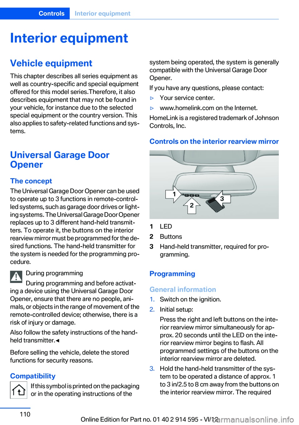
Controls on the interior rearview mirror
1LED2Buttons3Hand-held transmitter, required for pro‐
gramming.
Programming
General information
1.Switch on the ignition.2.Initial setup:
Press the right and left buttons on the inte‐
rior rearview mirror simultaneously for ap‐
prox. 20 seconds until the LED on the inte‐
rior rearview mirror begins to flash. All
programmed settings of the buttons on the
interior rearview mirror are deleted.3.Hold the hand-held transmitter of the sys‐
tem to be operated a distance of approx. 1
to 3 in/2.5 to 8 cm away from the buttons on
the interior rearview mirror. The requiredSeite 110ControlsInterior equipment110
Online Edition for Part no. 01 40 2 914 595 - VI/12
Page 126 of 291

Things to remember when drivingVehicle equipment
This chapter describes all series equipment as
well as country-specific and special equipment
offered for this model series.Therefore, it also
describes equipment that may not be found in
your vehicle, for instance due to the selected
special equipment or the country version. This
also applies to safety-related functions and sys‐
tems.
Breaking-in period
General information
Moving parts need to be broken in to adjust to
each other.
The following instructions will help achieve a
long vehicle life and good economy.
Engine and differential
Always obey all official speed limits.
Up to 1,200 miles/2,000 km
Do not exceed the maximum engine and road
speeds:▷For a gasoline engine, 4,500 rpm and
100 mph/160 km/h.
Avoid full-throttle operation and use of the
transmission's kickdown mode for the initial
miles.
From 1,200 miles/2,000 km
The engine and vehicle speed can gradually be
increased.
Tires
Due to technical factors associated with their
manufacture, tires do not achieve their full trac‐
tion potential until after an initial breaking-in pe‐
riod.
Drive conservatively for the first
200 miles/300 km.
Brake system
Brakes require an initial break-in period of ap‐
prox. 300 miles/500 km to achieve optimized
contact and wear patterns between brake pads
and rotors. Drive cautiously during this break-in
period.
Following part replacement
The same breaking in procedures should be ob‐
served if any of the components mentioned
above have to be renewed in the course of the
vehicle's operating life.
General driving notes
Closing tailgate Drive with the tailgate closed
Only drive with the tailgate closed; other‐
wise, passengers and other road users may be
endangered or the vehicle may be damaged if an
accident occurs or during braking or evasive
maneuvers. In addition, exhaust fumes may en‐
ter the passenger compartment.◀
If, despite this, the vehicle must be driven with
the tailgate open:▷Drive moderately.▷Close all windows and the panoramic glass
sunroof.▷Greatly increase the blower speed.
Hot exhaust system
Hot exhaust system
High temperatures are generated in the
exhaust system.
Seite 126Driving tipsThings to remember when driving126
Online Edition for Part no. 01 40 2 914 595 - VI/12