2013 BMW X1 XDRIVE 28I width
[x] Cancel search: widthPage 44 of 291
Seat tilt
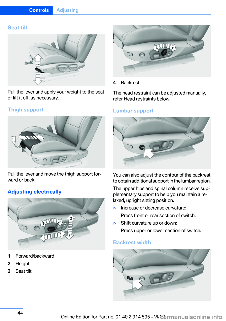
Pull the lever and apply your weight to the seat
or lift it off, as necessary.
Thigh support
Pull the lever and move the thigh support for‐
ward or back.
Adjusting electrically
1Forward/backward2Height3Seat tilt4Backrest
The head restraint can be adjusted manually,
refer Head restraints below.
Lumbar support
You can also adjust the contour of the backrest
to obtain additional support in the lumbar region.
The upper hips and spinal column receive sup‐
plementary support to help you maintain a re‐
laxed, upright sitting position.
▷Increase or decrease curvature:
Press front or rear section of switch.▷Shift curvature up or down:
Press upper or lower section of switch.
Backrest width
Seite 44ControlsAdjusting44
Online Edition for Part no. 01 40 2 914 595 - VI/12
Page 45 of 291
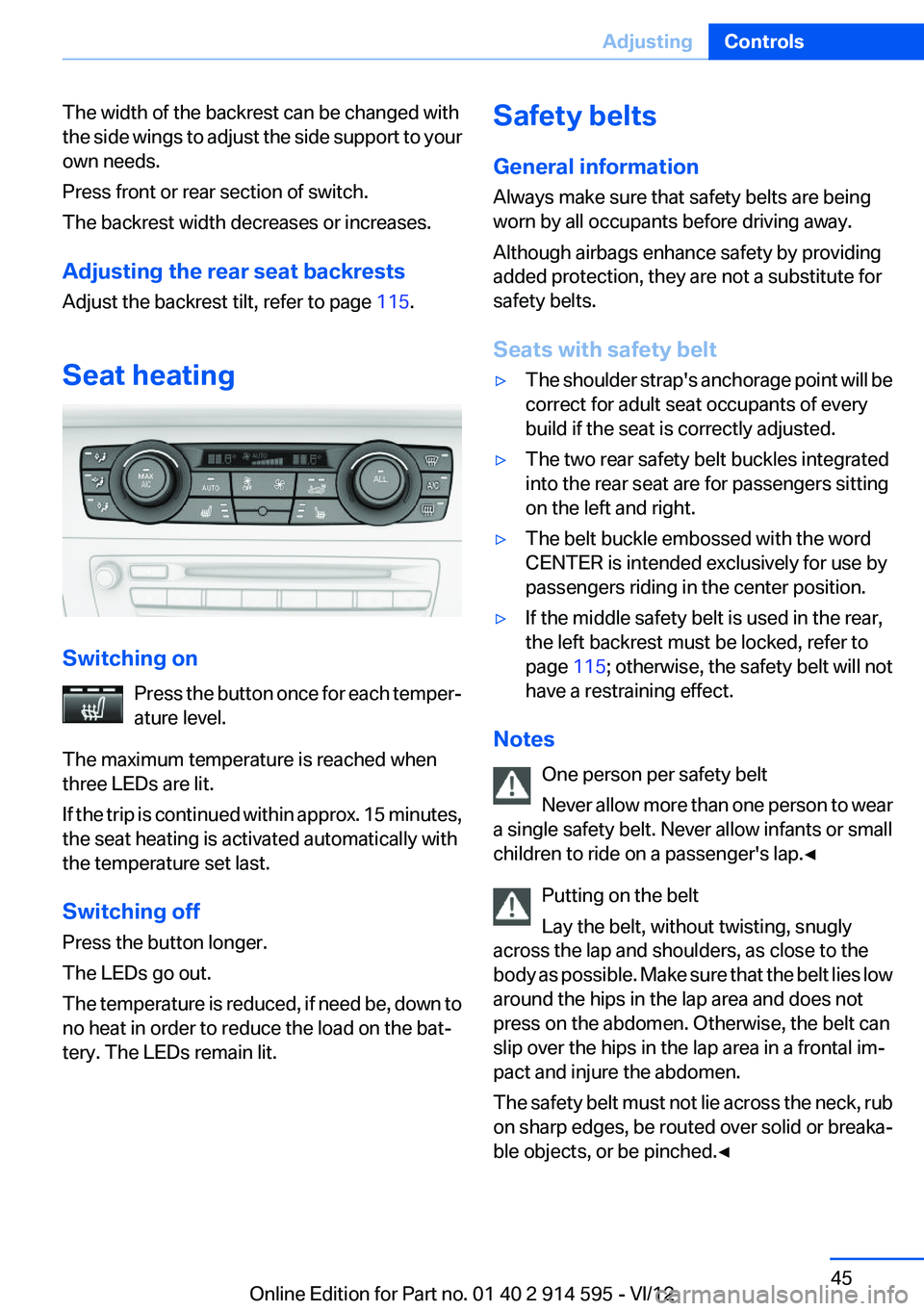
The width of the backrest can be changed with
the side wings to adjust the side support to your
own needs.
Press front or rear section of switch.
The backrest width decreases or increases.
Adjusting the rear seat backrests
Adjust the backrest tilt, refer to page 115.
Seat heating
Switching on Press the button once for each temper‐
ature level.
The maximum temperature is reached when
three LEDs are lit.
If the trip is continued within approx. 15 minutes,
the seat heating is activated automatically with
the temperature set last.
Switching off
Press the button longer.
The LEDs go out.
The temperature is reduced, if need be, down to
no heat in order to reduce the load on the bat‐
tery. The LEDs remain lit.
Safety belts
General information
Always make sure that safety belts are being
worn by all occupants before driving away.
Although airbags enhance safety by providing
added protection, they are not a substitute for
safety belts.
Seats with safety belt▷The shoulder strap's anchorage point will be
correct for adult seat occupants of every
build if the seat is correctly adjusted.▷The two rear safety belt buckles integrated
into the rear seat are for passengers sitting
on the left and right.▷The belt buckle embossed with the word
CENTER is intended exclusively for use by
passengers riding in the center position.▷If the middle safety belt is used in the rear,
the left backrest must be locked, refer to
page 115; otherwise, the safety belt will not
have a restraining effect.
Notes
One person per safety belt
Never allow more than one person to wear
a single safety belt. Never allow infants or small
children to ride on a passenger's lap.◀
Putting on the belt
Lay the belt, without twisting, snugly
across the lap and shoulders, as close to the
body as possible. Make sure that the belt lies low
around the hips in the lap area and does not
press on the abdomen. Otherwise, the belt can
slip over the hips in the lap area in a frontal im‐
pact and injure the abdomen.
The safety belt must not lie across the neck, rub
on sharp edges, be routed over solid or breaka‐
ble objects, or be pinched.◀
Seite 45AdjustingControls45
Online Edition for Part no. 01 40 2 914 595 - VI/12
Page 47 of 291
Rear
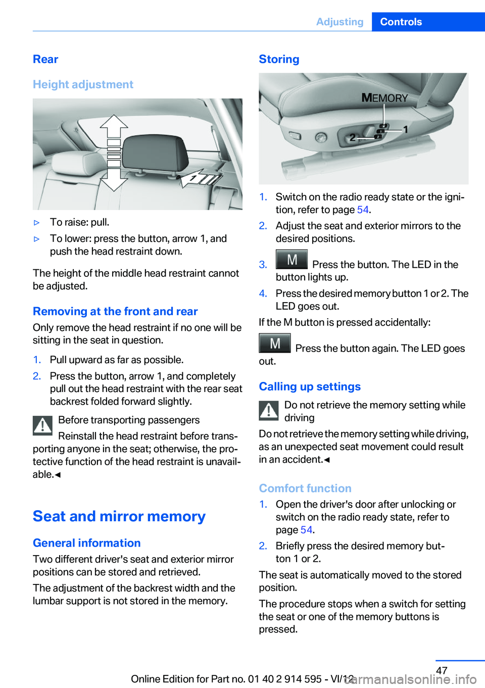
Height adjustment▷To raise: pull.▷To lower: press the button, arrow 1, and
push the head restraint down.
The height of the middle head restraint cannot
be adjusted.
Removing at the front and rear
Only remove the head restraint if no one will be
sitting in the seat in question.
1.Pull upward as far as possible.2.Press the button, arrow 1, and completely
pull out the head restraint with the rear seat
backrest folded forward slightly.
Before transporting passengers
Reinstall the head restraint before trans‐
porting anyone in the seat; otherwise, the pro‐
tective function of the head restraint is unavail‐
able.◀
Seat and mirror memory
General information
Two different driver's seat and exterior mirror
positions can be stored and retrieved.
The adjustment of the backrest width and the
lumbar support is not stored in the memory.
Storing1.Switch on the radio ready state or the igni‐
tion, refer to page 54.2.Adjust the seat and exterior mirrors to the
desired positions.3. Press the button. The LED in the
button lights up.4.Press the desired memory button 1 or 2. The
LED goes out.
If the M button is pressed accidentally:
Press the button again. The LED goes
out.
Calling up settings Do not retrieve the memory setting while
driving
Do not retrieve the memory setting while driving,
as an unexpected seat movement could result
in an accident.◀
Comfort function
1.Open the driver's door after unlocking or
switch on the radio ready state, refer to
page 54.2.Briefly press the desired memory but‐
ton 1 or 2.
The seat is automatically moved to the stored
position.
The procedure stops when a switch for setting
the seat or one of the memory buttons is
pressed.
Seite 47AdjustingControls47
Online Edition for Part no. 01 40 2 914 595 - VI/12
Page 49 of 291
Fold in the mirror in a car wash
Before entering an automatic car wash,
fold in the exterior mirrors by hand or with the
button; otherwise, they could be damaged, de‐
pending on the width of the vehicle.◀
Automatic heating
Depending on the external temperature, both
exterior mirrors are automatically heated when
the engine is running or the ignition is switched
on.
Interior rearview mirror
Reducing the blinding effect
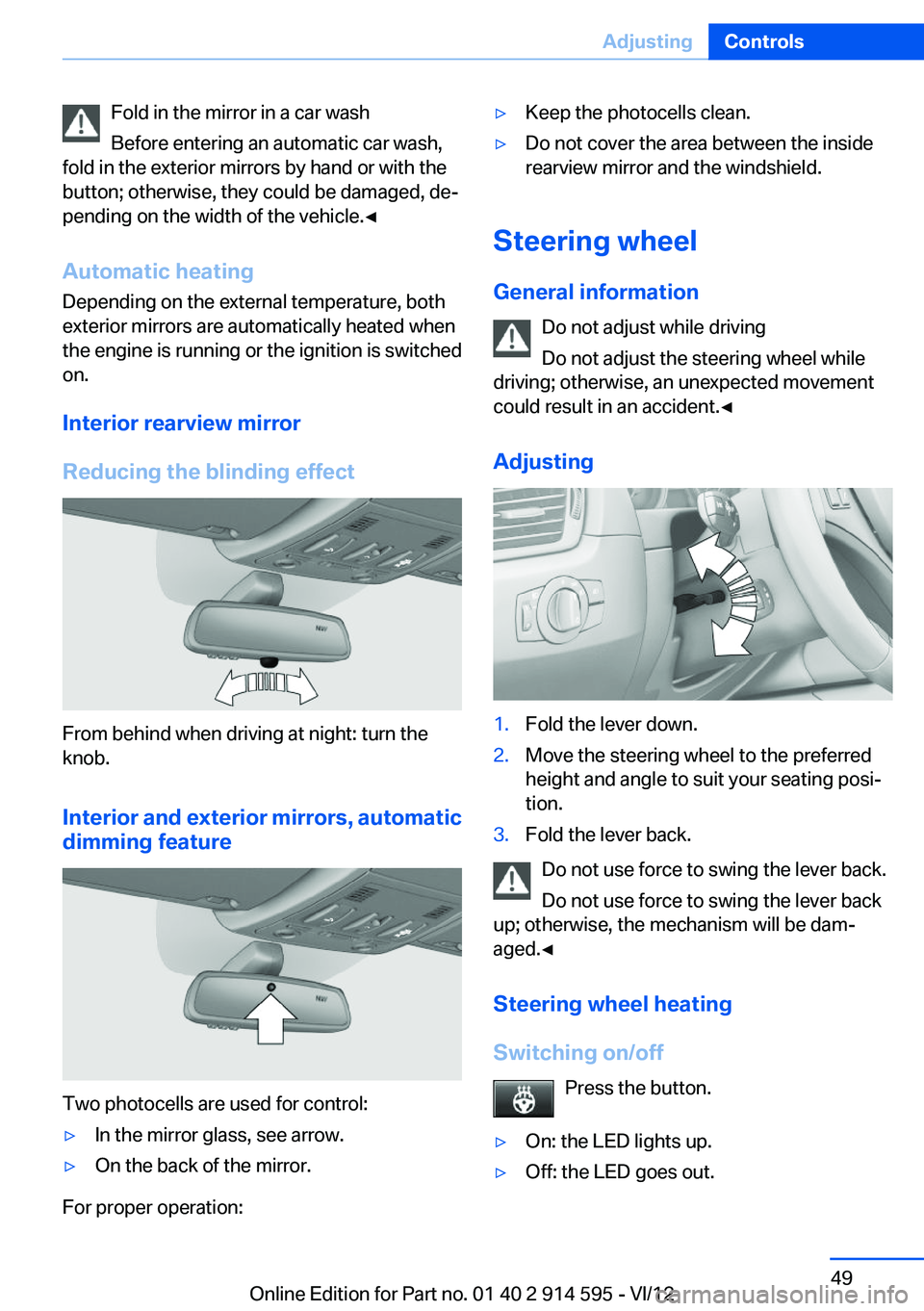
From behind when driving at night: turn the
knob.
Interior and exterior mirrors, automatic
dimming feature
Two photocells are used for control:
▷In the mirror glass, see arrow.▷On the back of the mirror.
For proper operation:
▷Keep the photocells clean.▷Do not cover the area between the inside
rearview mirror and the windshield.
Steering wheel
General information Do not adjust while driving
Do not adjust the steering wheel while
driving; otherwise, an unexpected movement
could result in an accident.◀
Adjusting
1.Fold the lever down.2.Move the steering wheel to the preferred
height and angle to suit your seating posi‐
tion.3.Fold the lever back.
Do not use force to swing the lever back.
Do not use force to swing the lever back
up; otherwise, the mechanism will be dam‐
aged.◀
Steering wheel heating
Switching on/off Press the button.
▷On: the LED lights up.▷Off: the LED goes out.Seite 49AdjustingControls49
Online Edition for Part no. 01 40 2 914 595 - VI/12
Page 51 of 291
possible and adjust its height to the highest po‐
sition to obtain the best possible position for the
belt and to offer optimal protection in the event
of an accident.
Do not change the seat position and height after
this.
Backrest width
Before mounting a child restraint fixing system
on the front passenger seat, open the backrest
width, refer to page 44, completely. Do not
change the backrest width after this.
Backrest width for the child seat
Before installing a child restraint fixing
system in the front passenger seat, the backrest
width must be opened completely. Do not
change the adjustment after this; otherwise, the
stability of the child seat will be reduced.◀
Child seat security
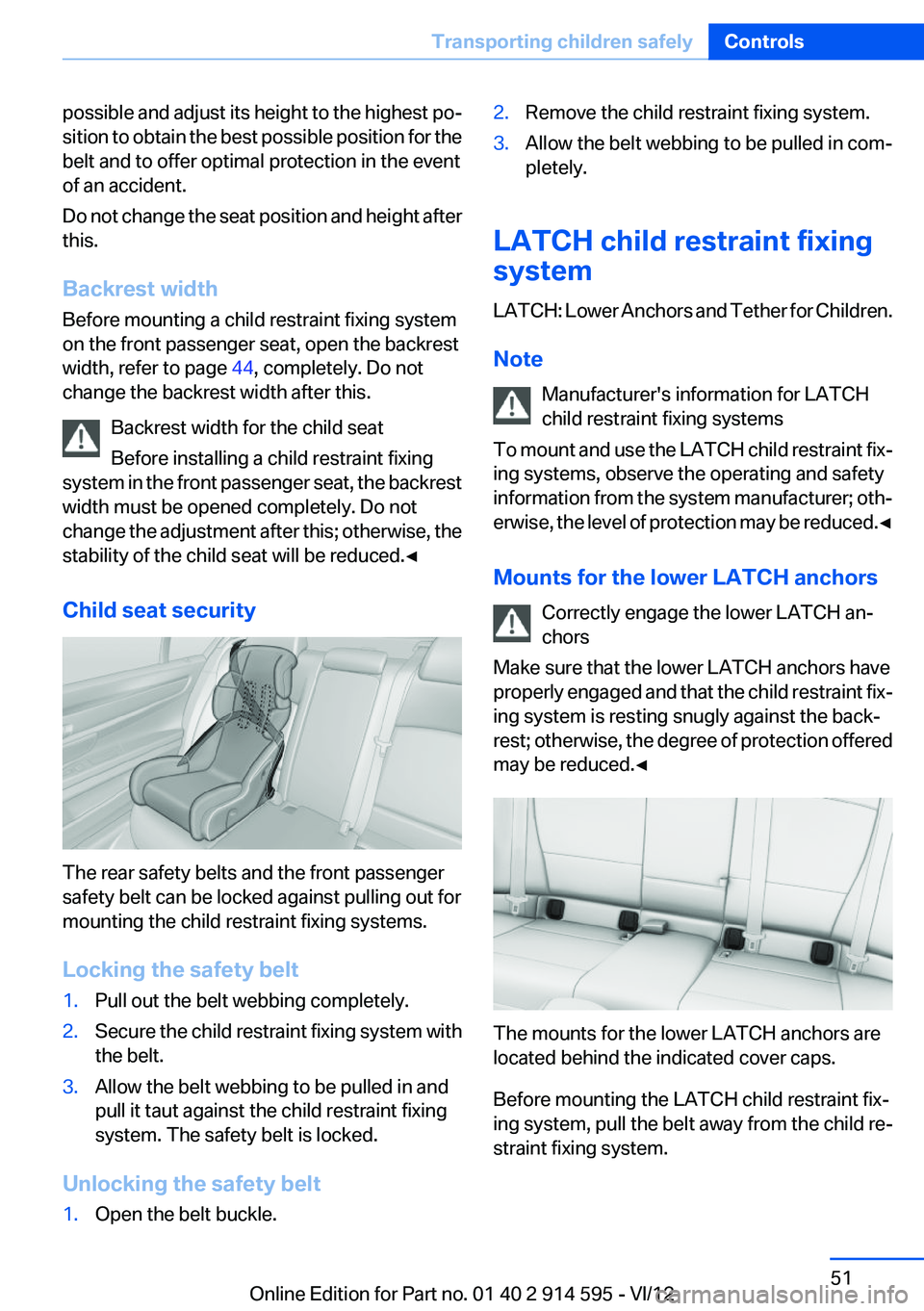
The rear safety belts and the front passenger
safety belt can be locked against pulling out for
mounting the child restraint fixing systems.
Locking the safety belt
1.Pull out the belt webbing completely.2.Secure the child restraint fixing system with
the belt.3.Allow the belt webbing to be pulled in and
pull it taut against the child restraint fixing
system. The safety belt is locked.
Unlocking the safety belt
1.Open the belt buckle.2.Remove the child restraint fixing system.3.Allow the belt webbing to be pulled in com‐
pletely.
LATCH child restraint fixing
system
LATCH: Lower Anchors and Tether for Children.
Note Manufacturer's information for LATCH
child restraint fixing systems
To mount and use the LATCH child restraint fix‐
ing systems, observe the operating and safety
information from the system manufacturer; oth‐
erwise, the level of protection may be reduced. ◀
Mounts for the lower LATCH anchors Correctly engage the lower LATCH an‐
chors
Make sure that the lower LATCH anchors have
properly engaged and that the child restraint fix‐
ing system is resting snugly against the back‐
rest; otherwise, the degree of protection offered
may be reduced.◀
The mounts for the lower LATCH anchors are
located behind the indicated cover caps.
Before mounting the LATCH child restraint fix‐
ing system, pull the belt away from the child re‐
straint fixing system.
Seite 51Transporting children safelyControls51
Online Edition for Part no. 01 40 2 914 595 - VI/12
Page 233 of 291

Tire sizePressure specifications in
bar/PSIFront: 225/40 R 19 89 W RSC
Rear: 255/35 R 19 92 W RSC3.0/44
--
3.2/46Compact wheel:
T 135/80 R 17 103 MSpeeds of up to 50 mph/
80 km/h
4.2/60Tire identification marks
Knowledge of the labeling on the side of the tire
makes it easier to identify and choose the right
tires.
Tire size
Example: 225/45 R 17 91 V
225: nominal width in mm
45: aspect ratio in %
R: radial tire code
17: rim diameter in inches
91: load rating, not for ZR tires
V: speed rating, before the R on ZR tires
Speed letter
Q = up to 100 mph/160 km/h
T = up to 118 mph/190 km/h
H = up to 131 mph/210 km/h
V = up to 150 mph/240 km/h
W = up to 167 mph/270 km/h
Y = up to 186 mph/300 km/h
Tire Identification Number
Tires with DOT codes meet the guidelines of the
U.S. Department of Transportation.
DOT code:
DOT xxxx xxx 1012
xxxx: manufacturer code for the tire brand
xxx: tire size and tire design
1012: tire ageTire age
The tire manufacturing date is contained in the
tire identification mark: DOT ... 1012 means that
the tire was manufactured in the week 10 of
2012.
BMW recommends that you replace all tires af‐
ter 6 years at most, even if some tires may last
for 10 years.
Uniform Tire Quality Grading
Quality grades can be found where applicable
on the tire sidewall between tread shoulder and
maximum section width. For example:
Treadwear 200 Traction AA
Temperature A
DOT Quality Grades
Treadwear
Traction AA A B C
Temperature A B C
Conform to Federal Safety Requirements
All passenger car tires must conform to
Federal Safety Requirements in addition to
these grades.◀
Treadwear
The treadwear grade is a comparative rating
based on the wear rate of the tire when tested
under controlled conditions on a specified gov‐
ernment test course. For example, a tire graded
150 would wear one and one-half (1 1/2) times
as well on the government course as a tire
graded 100. The relative performance of tiresSeite 233Wheels and tiresMobility233
Online Edition for Part no. 01 40 2 914 595 - VI/12
Page 259 of 291

CareVehicle equipment
This chapter describes all series equipment as
well as country-specific and special equipment
offered for this model series.Therefore, it also
describes equipment that may not be found in
your vehicle, for instance due to the selected
special equipment or the country version. This
also applies to safety-related functions and sys‐
tems.
Car washes
Notes Steam jets or high-pressure washers
When using steam jets or high-pressure
washers, hold them a sufficient distance away
and use a maximum temperature of
140 ℉/60 ℃.
Holding them too close or using excessively
high pressures or temperatures can cause dam‐
age or preliminary damage that may then lead to
long-term damage.
Follow the operating instructions for the high-
pressure washer.◀
Cleaning sensors/cameras with high-
pressure washers
When using high-pressure washers, do not
spray the exterior sensors and cameras, for Park
Distance Control or the backup camera, for in‐
stance, for extended periods of time and only
from a distance of at least 12 in/30 cm.◀
Wash your vehicle frequently, particularly in win‐
ter.
Intense soiling and road salt can damage the ve‐
hicle.Washing in automatic car washes
Give preference to cloth car washes or those
that use soft brushes in order to avoid paint
damage.
Notes
Note the following:▷Make sure that the wheels and tires are not
damaged by the transport mechanisms.▷Fold in the exterior mirrors; otherwise, they
may be damaged, depending on the width of
the vehicle.▷Deactivate the rain sensor, refer to page 60,
to avoid unintentional wiper activation.▷Move the rear window wiper to its resting
position, deactivate it, and protect it against
damage. Ask the car wash operator about
any necessary protective measures.▷Remove additional attachments, for in‐
stance a spoiler or telephone antenna, if
there is a risk that these may be damaged.
Guide rails in car washes
Avoid car washes with guide rails higher
than 4 in/10 cm; otherwise, the vehicle body
could be damaged.◀
Before driving into a car wash
The vehicle is able to roll if the following steps
are taken.
Automatic transmission
1.Insert the remote control into the ignition
lock, even with Comfort Access.2.Engage the selector lever or transmission
position N.3.Release the handbrake, refer to page 58.4.Switch the engine off.5.Leave the remote control in the ignition lock
so that the vehicle can roll.Seite 259CareMobility259
Online Edition for Part no. 01 40 2 914 595 - VI/12
Page 266 of 291

Technical dataVehicle equipment
This chapter describes all series equipment as
well as country-specific and special equipment
offered for this model series.Therefore, it alsodescribes equipment that may not be found in
your vehicle, for instance due to the selected
special equipment or the country version. This
also applies to safety-related functions and sys‐
tems.
Dimensions
1Vehicle width, without exterior mirrors:
70.8 inches/1,798 mm2Vehicle height: 60.8 inches/1,545 mm3Vehicle width, with exterior mirrors: 81 in‐
ches/2,058 mm4Wheelbase: 108.7 inches/2,760 mm5Vehicle length: 176.5 inches/4,484 mmSeite 266ReferenceTechnical data266
Online Edition for Part no. 01 40 2 914 595 - VI/12