2013 BMW M5 SEDAN radio
[x] Cancel search: radioPage 67 of 230
DrivingVehicle equipment
All standard, country-specific and optional
equipment that is offered in the model series is
described in this chapter. Therefore, equip‐
ment is also described that is not available in a
vehicle, e. g., because of the selected optional
equipment or country variant. This also applies
for safety-related functions and systems.
Start/Stop button The concept Pressing the Start/Stop button
switches the ignition on or off
and starts the engine.
Double-clutch transmission:
The engine starts if the brake is
depressed while pressing the Start/Stop but‐
ton.
Manual transmission: the engine starts if the
clutch pedal is depressed when the Start/Stop
button is pressed.
Ignition onDouble-clutch transmission: Press the Start/
Stop button but do not depress the brake.
Manual-shift transmission: press the Start/
Stop button, and do not press on the clutch
pedal at the same time.
All vehicle systems are ready for operation.
Most of the indicator and warning lamps in the
instrument cluster light up for varying lengths
of time.
To save battery power when the engine is off,
switch off the ignition and any unnecessary
electronic systems/power consumers.
The ignition switches off automatically:▷When locking the vehicle, even if the low
beams are switched on.▷Shortly before the battery is discharged
completely, so that the engine can still be
started.
Note
If the engine is switched off and the ignition is
switched on, the system automatically
switches to the radio ready state when the
door is opened if the lights are switched off or
the daytime running lights are switched on.
Ignition off
Double-clutch transmission: Press the Start/
Stop button again, but do not depress the
brake.
Manual-shift transmission: press the Start/
Stop button again, and do not press on the
clutch pedal at the same time.
All indicator lamps in the instrument cluster go
out.
To save battery power when the engine is off,
switch off the ignition and any unnecessary
electronic systems/power consumers.
Transmission position P with the ignition
off
When the ignition is switched off, position P is
engaged automatically. When in an automatic
car wash, for example, ensure that the ignition
is not switched off accidentally.◀
The ignition automatically cuts off while the
vehicle is stationary and the engine is stopped:
▷When locking the vehicle, and when the
low beams are activated.▷Shortly before the battery is discharged
completely, so that the engine can still be
started. This function is only available
when the low beams are switched off.Seite 63DrivingControls63
Online Edition for Part no. 01 40 2 909 953 - VI/13
Page 68 of 230
▷When opening or closing the driver door, if
the driver's seat belt is unbuckled and the
low beams are switched off.▷While the driver's seat belt is unbuckled, if
the driver's door is open and the low
beams are switched off.
When the ignition is switched off, by opening
or closing the driver's door or unbuckling the
driver's seat belt, the radio ready state remains
active.
Radio ready state
Activate radio ready state:
▷When the engine is running: press the
Start/Stop button.
Some electronic systems/power consumers
remain ready for operation.
The radio ready state switches off automati‐
cally:
▷After approx. 8 minutes.▷When the vehicle is locked using the cen‐
tral locking system.▷Shortly before the battery is discharged
completely, so that the engine can still be
started.
Starting the engine
Hints Enclosed areas
Do not let the engine run in enclosed
areas; otherwise, breathing of exhaust fumes may lead to loss of consciousness and death.
The exhaust gases contain carbon monoxide,
an odorless and colorless but highly toxic
gas.◀
Unattended vehicle
Do not leave the vehicle unattended with
the engine running; doing so poses a risk of
danger.
Before leaving the vehicle with the engine run‐
ning, set the parking brake and engage trans‐
mission position P; otherwise, the vehicle may
begin to roll.◀
Repeated starting in quick succession
Avoid repeated unsuccessful attempts to
start the vehicle or starting the vehicle several
times in quick succession. Otherwise, the fuel
is not burned or is inadequately burned, posing
a risk of overheating and damage to the cata‐
lytic converter.◀
Do not wait for the engine to warm-up while
the vehicle remains stationary. Start driving at
moderate engine speeds.
Manual transmission
Starting the engine1.Depress the brake pedal.2.Press on the clutch pedal and shift to neu‐
tral.3.Press the Start/Stop button.
The ignition is activated automatically for a
certain time and is stopped as soon as the en‐
gine starts.
Double-clutch transmission
Starting the engine
1.Depress the brake pedal.2.Press the Start/Stop button.
The ignition is activated automatically for a
certain time and is stopped as soon as the en‐
gine starts.
Seite 64ControlsDriving64
Online Edition for Part no. 01 40 2 909 953 - VI/13
Page 69 of 230
Engine stop
Hints Take the remote control with youTake the remote control with you when
leaving the vehicle so that children, for exam‐
ple, cannot start the engine.◀
Set the parking brake and further secure
the vehicle as required
Set the parking brake firmly when parking; oth‐
erwise, the vehicle could roll. On steep upward
and downward inclines, further secure the ve‐
hicle, for example, by turning the steering
wheel in the direction of the curb. ◀
Before driving into a car wash
In order for the vehicle to be able to roll into a
car wash, heed the information regarding
Washing in automatic car washes, refer to
page 205.
Manual transmission
Switching off the engine1.With the vehicle at a standstill, press the
Start/Stop button.2.Shift into first gear or reverse.3.Set the parking brake.
Double-clutch transmission
Switching off the engine
1.Apply the brakes until the vehicle comes to
a stop.2.Press the Start/Stop button.
The engine is switched off.
The radio ready state is switched on.3.Set the parking brake.Automatic Engine Start/Stop
Function
The concept The Auto Start/Stop function helps save fuel.
The system switches off the engine during a
stop, e.g., in a traffic congestion or at traffic
lights. The ignition remains switched on. The
engine starts again automatically for driving
off.
Certain vehicle components may experience
additional wear as a result of this system.
Semi-automatic mode
After every start of the engine, the Auto Start
Stop function is in the last selected state, refer
to page 67. When the Auto Start Stop func‐
tion is active, it is available when the vehicle is
traveling faster than about 3 mph, approx.
5 km/h.
Engine stop
The engine is switched off automatically dur‐
ing a stop under the following conditions:
Manual transmission:▷Neutral is engaged and the clutch pedal is
not pressed.▷The driver's seat belt is buckled or the driv‐
er's door is closed.
Double-clutch transmission:
▷The selector lever is in transmission posi‐
tion D.▷Brake pedal remains depressed while the
vehicle is stopped.▷The driver's seat belt is buckled or the driv‐
er's door is closed.
The air volume of the air conditioner is reduced
when the engine is switched off.
Seite 65DrivingControls65
Online Edition for Part no. 01 40 2 909 953 - VI/13
Page 83 of 230

Electronic displays
Overview, instrument cluster1Messages, e.g. Check Control 79
Time 82
Digital tachometer 822Range 833Computer 884Transmission display, Drivelogic 83
Gear shift indicator 86
Service requirements 84Miles/trip miles 825Selection list, such as for the radio 88
System states of driving dynamics 84
Current fuel consumption 83
Energy recovery 83
External temperature 82
Auto Start/Stop function 65Check Control
The concept The Check Control system monitors functions
in the vehicle and notifies you of malfunctions
in the monitored systems.
A Check Control message is displayed as a
combination of indicator or warning lamps and
text messages in the instrument cluster and in
the Head-up Display.In addition, an acoustic signal may be output
and a text message may appear on the Control Display.
Indicator/warning lamps The indicator and warning lamps in the instru‐
ment cluster can light up in a variety of combi‐
nations and colors.
Several of the lamps are checked for proper
functioning and light up temporarily when the
engine is started or the ignition is switched on.Seite 79DisplaysControls79
Online Edition for Part no. 01 40 2 909 953 - VI/13
Page 106 of 230
The tire pressure depends on the temperature
of the tire. If the tire temperature rises, e.g.,
due to driving or because of the heat of the
Sun, the tire inflation pressure increases also.
The tire pressure is reduced when the tire
temperature falls again. This behavior may
cause a warning to be issued if temperatures
fall very sharply.
Malfunction The yellow warning lamp flashes and
then lights up continuously. A Check
Control message is displayed. No flat
tire or loss of tire pressure can be detected.
Display in the following situations:▷A wheel without TPM electronics is fitted:
have the service center check it if neces‐
sary.▷Malfunction: have the system checked by
your service center.▷TPM was unable to complete the reset.
Reset the system again.▷Disturbance by systems or devices with
the same radio frequency: after leaving the
area of the disturbance, the system auto‐
matically becomes active again.
Declaration according to NHTSA/
FMVSS 138 Tire Pressure Monitoring
System
Each tire, including the spare (if provided)
should be checked monthly when cold and in‐
flated to the inflation pressure recommended
by the vehicle manufacturer on the vehicle
placard or tire inflation pressure label. (If your
vehicle has tires of a different size than the size
indicated on the vehicle placard or tire inflation
pressure label, you should determine the
proper tire inflation pressure for those tires.)
As an added safety feature, your vehicle has
been equipped with a tire pressure monitoring
system (TPMS) that illuminates a low tire pres‐
sure telltale when one or more of your tires is
significantly under-inflated. Accordingly, when
the low tire pressure telltale illuminates, you
should stop and check your tires as soon as
possible, and inflate them to the proper pres‐
sure. Driving on a significantly under-inflated
tire causes the tire to overheat and can lead to
tire failure. Under-inflation also reduces fuel ef‐
ficiency and tire tread life, and may affect the
vehicle's handling and stopping ability. Please
note that the TPMS is not a substitute for
proper tire maintenance, and it is the driver's
responsibility to maintain correct tire pressure,
even if under-inflation has not reached the
level to trigger illumination of the TPMS low
tire pressure telltale. Your vehicle has also
been equipped with a TPMS malfunction indi‐
cator to indicate when the system is not oper‐
ating properly. The TPMS malfunction indica‐
tor is combined with the low tire pressure
telltale. When the system detects a malfunc‐
tion, the telltale will flash for approximately one
minute and then remain continuously illumi‐
nated. This sequence will continue upon sub‐
sequent vehicle start-ups as long as the mal‐
function exists. When the malfunction indicator
is illuminated, the system may not be able to
detect or signal low tire pressure as intended.
TPMS malfunctions may occur for a variety of
reasons, including the installation of replace‐
ment or alternate tires or wheels on the vehicle
that prevent the TPMS from functioning prop‐
erly. Always check the TPMS malfunction tell‐
tale after replacing one or more tires or wheels
on your vehicle to ensure that the replacement
or alternate tires and wheels allow the TPMS
to continue to function properly.
FTM Flat Tire Monitor The conceptThe system does not measure the actual infla‐
tion pressure in the tires.
It detects a pressure loss in a tire by comparing
the rotational speeds of the individual wheels
while moving.Seite 102ControlsSafety102
Online Edition for Part no. 01 40 2 909 953 - VI/13
Page 201 of 230

Jacking points for the vehicle jack
The jacking points for the vehicle jack are lo‐
cated at the positions shown.
Vehicle battery Maintenance
The battery is maintenance-free, i.e., the elec‐
trolyte will last for the life of the battery.
Your service center will be glad to advise you
on questions regarding the battery.
Battery replacement Use approved vehicle batteries only
Only use vehicle batteries that have been
approved for your vehicle by the manufacturer;
otherwise, the vehicle could be damaged and
systems or functions may not be fully availa‐
ble.◀
After a battery replacement, have the battery
registered on the vehicle by your service cen‐
ter to ensure that all comfort functions are fully
available and that any Check Control mes‐
sages of these comfort functions are no longer
displayed.
Charging the battery
Note Do not plug chargers into the socketDo not connect battery chargers to the
factory-installed sockets in the vehicle as this
may damage the battery.◀
General information Make sure that the battery is always suffi‐
ciently charged to guarantee that the battery
remains usable for its full service life.
The battery may need to be charged in the fol‐
lowing cases:▷When making frequent short-distance
drives.▷If the vehicle is not used for prolonged pe‐
riods, longer than a month.
Starting aid terminals
In the vehicle, only charge the battery via the
starting aid terminals, refer to page 201, in the
engine compartment with the engine off.
Power failure After a temporary power loss, some equipment
needs to be reinitialized.
Individual settings need to be reprogrammed:
▷Seat, mirror, and steering wheel memory:
store the positions again.▷Time: update.▷Date: update.▷Radio station: saving new, see user's
manual for Navigation, Entertainment and
Communication.▷Navigation system: wait for the operability
of the navigation.
Disposing of old batteries
Have old batteries disposed of by your
service center or bring them to a recy‐
cling center.
Seite 197Replacing componentsMobility197
Online Edition for Part no. 01 40 2 909 953 - VI/13
Page 203 of 230
Breakdown assistanceVehicle equipment
All standard, country-specific and optional
equipment that is offered in the model series is
described in this chapter. Therefore, equip‐
ment is also described that is not available in a
vehicle, e. g., because of the selected optional
equipment or country variant. This also applies
for safety-related functions and systems.
Hazard warning flashers
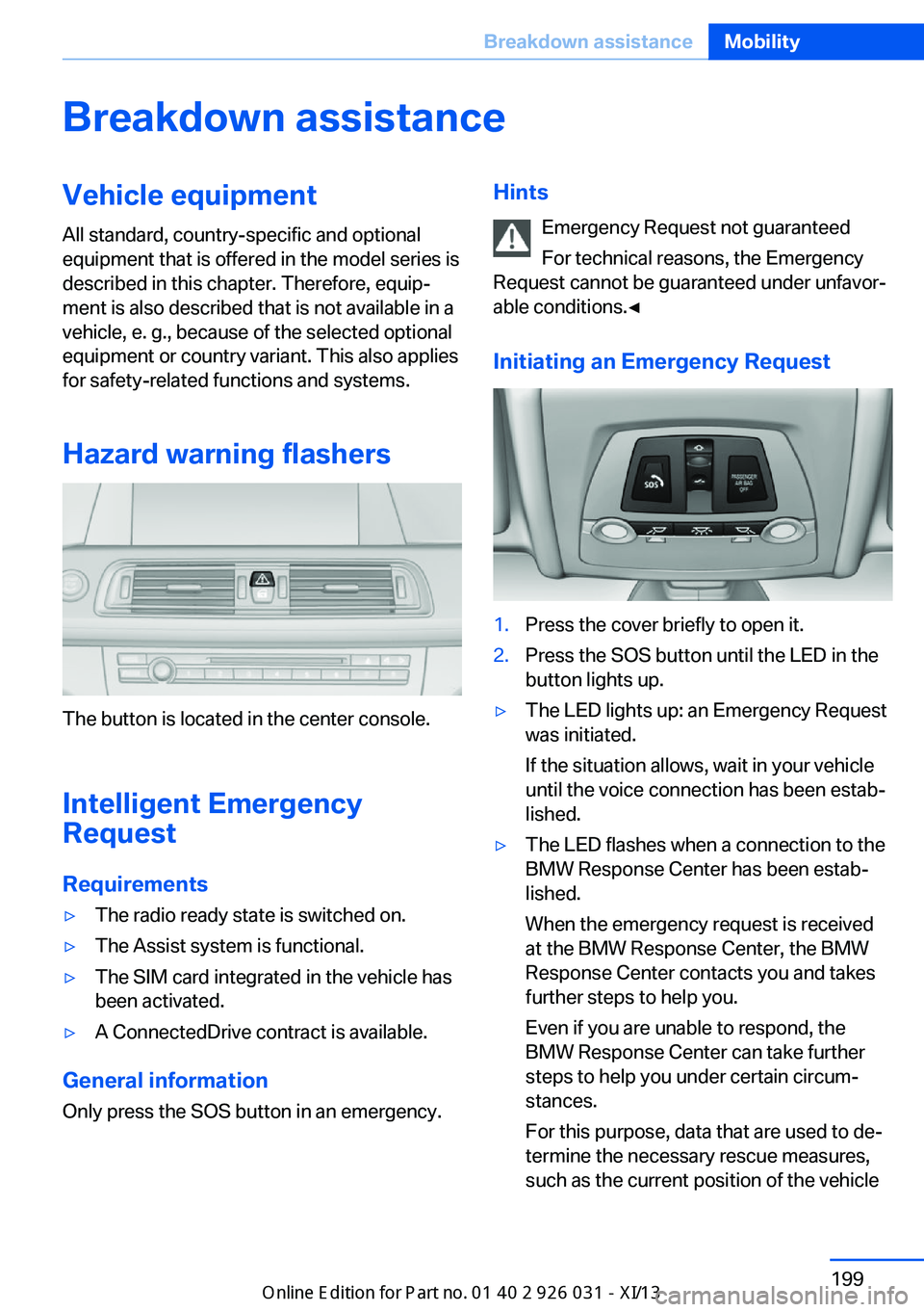
The button is located in the center console.
Intelligent Emergency
Request
Requirements
▷The radio ready state is switched on.▷The Assist system is functional.▷The SIM card integrated in the vehicle has
been activated.▷A ConnectedDrive contract is available.
General information
Only press the SOS button in an emergency.
Hints
Emergency Request not guaranteed
For technical reasons, the Emergency
Request cannot be guaranteed under unfavor‐
able conditions.◀
Initiating an Emergency Request1.Press the cover briefly to open it.2.Press the SOS button until the LED in the
button lights up.▷The LED lights up: an Emergency Request
was initiated.
If the situation allows, wait in your vehicle
until the voice connection has been estab‐
lished.▷The LED flashes when a connection to the
BMW Response Center has been estab‐
lished.
When the emergency request is received
at the BMW Response Center, the BMW
Response Center contacts you and takes
further steps to help you.
Even if you are unable to respond, the
BMW Response Center can take further
steps to help you under certain circum‐
stances.
For this purpose, data that are used to de‐
termine the necessary rescue measures,
such as the current position of the vehicleSeite 199Breakdown assistanceMobility199
Online Edition for Part no. 01 40 2 909 953 - VI/13
Page 226 of 230
Parked vehicle, condensa‐tion 163
Parking aid, refer to PDC 123
Parking brake 67
Parking lamps 92
Passenger side mirror, tilting downward 55
Pathway lines, rearview cam‐ era 127
PDC Park Distance Con‐ trol 123
Pedestrian detection, refer to Night Vision 108
Pedestrian warning with city braking function 106
People detection, refer to Night Vision 108
Permissible axle load 213
Personal Profile 31
Pinch protection system, glass sunroof 46
Pinch protection system, win‐ dows 44
Plastic, care 207
Power failure 197
Power sunroof, glass 45
Power windows 43
Pressure, tire air pres‐ sure 175
Pressure warning FTM, tires 102
Preventing Auto Start Stop 66
Profile, refer to Personal Pro‐ file 31
Programmable memory but‐ tons, iDrive 21
Protective function, glass sunroof 46
Protective function, win‐ dows 44
Push-and-turn switch, refer to Controller 16 R
Radiator fluid 189
Radio-operated key, refer to Remote control 30
Radio ready state 64
Radio, see user's manual for Navigation, Entertainment
and Communication
Rain sensor 70
Rear automatic climate con‐ trol 138
Rear lamps 195
Rear socket 145
Rearview mirror 55
Rear window defroster 136
Recirculated-air mode 136
Recommended tire brands 179
Refueling 172
Remaining range 83
Remote control/key 30
Remote control, malfunc‐ tion 35
Remote control, univer‐ sal 141
Replacement fuse 198
Replacing parts 192
Replacing wheels/tires 179
Reporting safety defects 9
Reserve warning, refer to Range 83
Reset, Tire Pressure Monitor TPM 101
Residual heat, automatic cli‐ mate control 136
Retaining straps, securing cargo 165
Retreaded tires 180
Reversing lamp, bulb replace‐ ment 195
Roadside parking lamps 93
Roller sunblinds 45
RON gasoline quality 174
Roof load capacity 213 Roof-mounted luggage
rack 165
Rope for tow-starting/ towing 203
Rubber components, care 207
S Safe braking 162
Safety 7
Safety belt reminder for driv‐ er's seat and front passen‐
ger seat 52
Safety belts 51
Safety belts, care 207
Safety Package, refer to Ac‐ tive Protection 114
Safety switch, windows 44
Safety systems, airbags 97
Saving fuel 167
Screen, refer to Control Dis‐ play 16
Screwdriver 192
Screw thread for tow fit‐ ting 204
Sealant 180
Seat belts, refer to Safety belts 51
Seat heating, front 50
Seat heating, rear 50
Seating position for chil‐ dren 59
Seat, mirror, and steering wheel memory 54
Seats 48
Seat ventilation, front 50
Selection list in instrument cluster 88
Selector lever 72
Sensors, care 208
Sequential mode 73
Service and warranty 7
Service history 85 Seite 222ReferenceEverything from A to Z222
Online Edition for Part no. 01 40 2 909 953 - VI/13