2013 BMW ACTIVEHYBRID3 ECU
[x] Cancel search: ECUPage 72 of 220

Engaging the transmission position▷Transmission position P can only be disen‐
gaged if the engine is running and the brake
pedal is pressed.▷With the vehicle stationary, press on the
brake pedal before shifting out of P or N;
otherwise, the shift command will not be
executed: shift lock.
Depress the brake until you start driv‐
ing
To prevent the vehicle from creeping after
you select a driving position, maintain pres‐
sure on the brake pedal until you are ready
to start.◀
Engaging D, R and N
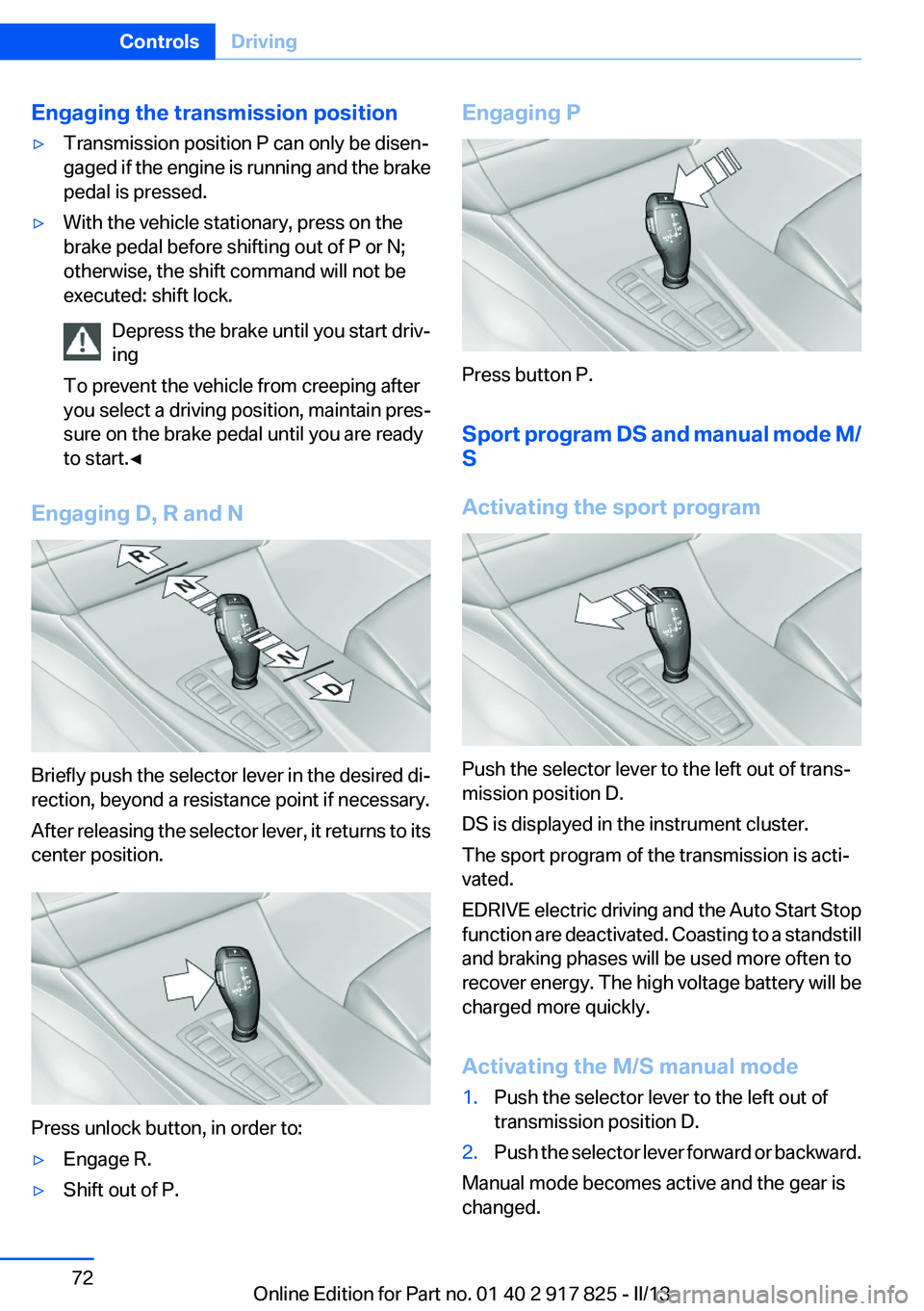
Briefly push the selector lever in the desired di‐
rection, beyond a resistance point if necessary.
After releasing the selector lever, it returns to its
center position.
Press unlock button, in order to:
▷Engage R.▷Shift out of P.Engaging P
Press button P.
Sport program DS and manual mode M/
S
Activating the sport program
Push the selector lever to the left out of trans‐
mission position D.
DS is displayed in the instrument cluster.
The sport program of the transmission is acti‐
vated.
EDRIVE electric driving and the Auto Start Stop
function are deactivated. Coasting to a standstill
and braking phases will be used more often to
recover energy. The high voltage battery will be
charged more quickly.
Activating the M/S manual mode
1.Push the selector lever to the left out of
transmission position D.2.Push the selector lever forward or backward.
Manual mode becomes active and the gear is
changed.
Seite 72ControlsDriving72
Online Edition for Part no. 01 40 2 917 825 - II/13
Page 77 of 220

Text messages
Text messages in combination with a symbol in
the instrument cluster explain a Check Control
message and the meaning of the indicator and
warning lamps.
Supplementary text messages
Addition information, such as on the cause of a
fault or the required action, can be called up via
Check Control.
The supplementary text of urgent messages is
displayed on the Control Display automatically.
Symbols
Depending on the Check Control message, the
following functions can be selected.▷ "Owner's Manual"
Display additional information about the
Check Control message in the Integrated
Owner's Manual.▷ "Service request"
Contact the service partner.▷ "Roadside Assistance"
Contact Roadside Assistance.
Hiding Check Control messages
Press the computer button on the turn signal
lever.
▷Some Check Control messages are dis‐
played continuously and are not cleared un‐
til the malfunction is eliminated. If several
malfunctions occur at once, the messages
are displayed consecutively.These messages can be hidden for approx.
8 seconds. After this time, they are dis‐
played again automatically.▷Other Check Control messages are hidden
automatically after approx. 20 seconds.
They are stored and can be displayed again
later.
Displaying stored Check Control
messages
1."Vehicle Info"2."Vehicle status"3. "Check Control"4.Select the text message.
Messages after trip completion
Special messages that are displayed during
driving are displayed again after the ignition is
switched off.
Fuel gauge The vehicle inclination may
cause the display to vary.
US models: the arrow beside the
fuel pump symbol shows which
side of the vehicle the fuel filler
flap is on.
Hints on refueling, refer to page 166.
Tachometer
Always avoid engine speeds in the red warning
field. In this range, the fuel supply is interrupted
to protect the engine.
Seite 77DisplaysControls77
Online Edition for Part no. 01 40 2 917 825 - II/13
Page 110 of 220

If the belt tension does not loosen automatically,
stop the vehicle and unbuckle the belt using the
red button in the buckle. Fasten the belt before
continuing on your trip.
PostCrash
If an accident above a certain degree of severity,
the system automatically brakes the vehicle to a
standstill. This can reduce the risk of a further
collision and the consequences thereof.
Depressing the brake pedal can cause the vehi‐
cle to brake harder. This interrupts automatic
braking. Depressing the accelerator pedal also
interrupts automatic braking.
After coming to a halt, the brake is released au‐
tomatically. Secure the vehicle against rolling.Seite 110ControlsSafety110
Online Edition for Part no. 01 40 2 917 825 - II/13
Page 138 of 220

Interior equipmentVehicle equipment
All standard, country-specific and optional
equipment that is offered in the model series is
described in this chapter. Therefore, equipment
is also described that is not available in a vehicle,
e. g., because of the selected optional equip‐
ment or country variant. This also applies for
safety-related functions and systems.
Integrated universal remote
control
The concept
The integrated universal remote control can op‐
erate up to 3 functions of remote-controlled sys‐
tems such as garage door drives or lighting sys‐
tems. The integrated universal remote control
replaces up to 3 different hand-held transmit‐
ters. To operate the remote control, the buttons
on the interior rearview mirror must be program‐
med with the desired functions. The hand-held
transmitter for the particular system is required
in order to program the remote control.
During programming
During programming and before activat‐
ing a device using the integrated universal re‐
mote control, ensure that there are no people,
animals, or objects in the range of movement of
the remote-controlled device; otherwise, there
is a risk of injury or damage.
Also follow the safety instructions of the hand-
held transmitter.◀
Before selling the vehicle, delete the stored
functions for the sake of security.
Compatibility If this symbol is printed on the packaging
or in the instructions of the system to be
controlled, the system is generally com‐patible with the integrated universal remote
control.
If you have any questions, please contact:▷Your service center.▷www.homelink.com on the Internet.
HomeLink is a registered trademark of Johnson
Controls, Inc.
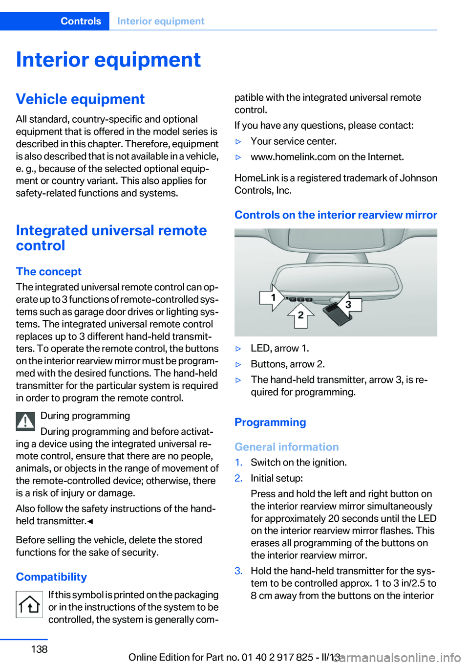
Controls on the interior rearview mirror
▷LED, arrow 1.▷Buttons, arrow 2.▷The hand-held transmitter, arrow 3, is re‐
quired for programming.
Programming
General information
1.Switch on the ignition.2.Initial setup:
Press and hold the left and right button on
the interior rearview mirror simultaneously
for approximately 20 seconds until the LED
on the interior rearview mirror flashes. This
erases all programming of the buttons on
the interior rearview mirror.3.Hold the hand-held transmitter for the sys‐
tem to be controlled approx. 1 to 3 in/2.5 to
8 cm away from the buttons on the interiorSeite 138ControlsInterior equipment138
Online Edition for Part no. 01 40 2 917 825 - II/13
Page 144 of 220

With Professional navigation system or
TV: at a glance
The USB interface is located in the center arm‐
rest.
Notes
Observe the following when connecting:
▷Do not use force when plugging the con‐
nector into the USB interface.▷Do not connect devices such as fans or
lamps to the USB interface.▷Do not connect USB hard drives.▷Do not use the USB interface to recharge
external devices.
Through-loading system
The concept
The cargo area can be enlarged by folding down
the rear seat backrest.
The rear seat backrest is divided at a ratio of 40–
20–40.
The sides can be folded down separately or to‐
gether.
Hints Danger of pinching
Before folding down the rear seat back‐
rests, ensure that the area of movement of the
backrests is clear. In particular, ensure that no
one is located in or reaches into the area of
movement of the rear seat backrests when the
middle section is folded down. Otherwise, injury
or damage may result.◀
Lock the rear seat backrests in position
Before mounting child restraint fixing sys‐
tems, place the seat backrest as far as possible
at an angle at which the child seat is resting
firmly against the backrest and all backrests can
be locked securely in place. Otherwise, the child
seat will not be as stable as it should be, and
there is increased danger of injury due to unex‐
pected movement of the seat backrest.◀
Retract the head restraint if necessary be‐
fore backrest is folded down
With folding head restraints, fold in the head re‐
straints before folding down the backrests, or
damage may result.◀
Opening1.Unlock the belt lock of the center safety belt
in the rear using the latch plate of another
safety belt.2.Insert the latch plate at the end of the belt
into the specially designated fixture on the
rear window shelf.3.Push the corresponding head restraint
down as far as it will go.Seite 144ControlsInterior equipment144
Online Edition for Part no. 01 40 2 917 825 - II/13
Page 145 of 220

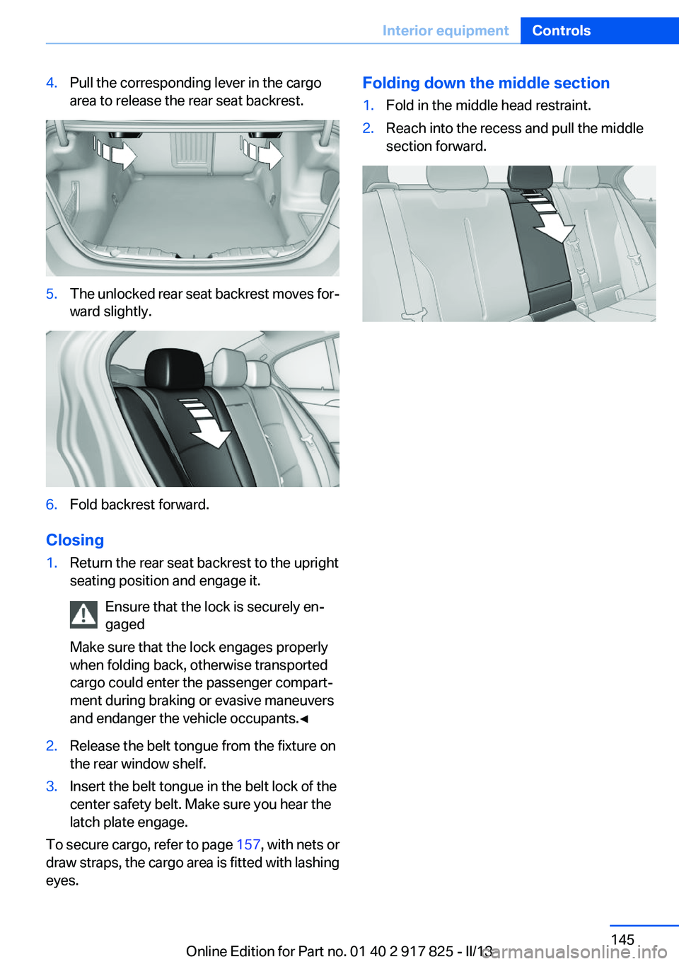
4.Pull the corresponding lever in the cargo
area to release the rear seat backrest.5.The unlocked rear seat backrest moves for‐
ward slightly.6.Fold backrest forward.
Closing
1.Return the rear seat backrest to the upright
seating position and engage it.
Ensure that the lock is securely en‐
gaged
Make sure that the lock engages properly
when folding back, otherwise transported
cargo could enter the passenger compart‐
ment during braking or evasive maneuvers
and endanger the vehicle occupants.◀2.Release the belt tongue from the fixture on
the rear window shelf.3.Insert the belt tongue in the belt lock of the
center safety belt. Make sure you hear the
latch plate engage.
To secure cargo, refer to page 157, with nets or
draw straps, the cargo area is fitted with lashing
eyes.
Folding down the middle section1.Fold in the middle head restraint.2.Reach into the recess and pull the middle
section forward.Seite 145Interior equipmentControls145
Online Edition for Part no. 01 40 2 917 825 - II/13
Page 146 of 220

Storage compartmentsVehicle equipment
All standard, country-specific and optional
equipment that is offered in the model series is
described in this chapter. Therefore, equipment
is also described that is not available in a vehicle,
e. g., because of the selected optional equip‐
ment or country variant. This also applies for
safety-related functions and systems.
Notes No loose objects in the passenger com‐
partment
Do not stow any objects in the passenger com‐
partment without securing them; otherwise,
they may present a danger to occupants for in‐
stance during braking and avoidance maneu‐
vers.◀
Do not place anti-slip mats on the dash‐
board
Do not place anti-slip mats on the dashboard.
The mat materials could damage the dash‐
board.◀
Storage compartments
The following storage compartments are avail‐
able in the vehicle interior:▷Glove compartment on the driver's side, re‐
fer to page 146.▷Glove compartment on the front passenger
side, refer to page 147.▷Without Smoker's package: Front storage
compartment, in front of the cupholders, re‐
fer to page 147.▷Storage compartment in the front center
armrest, refer to page 147.▷Compartments in the doors, refer to
page 147.▷Nets on the backrests of the front seats.
Glove compartment
Driver's side
Opening
Pull the handle. Close the glove compartment again im‐
mediately
Close the glove compartment immediately after
use while driving; otherwise, injury may occur
during accidents.◀
Closing
Fold up the cover.
Seite 146ControlsStorage compartments146
Online Edition for Part no. 01 40 2 917 825 - II/13
Page 147 of 220

Front passenger side
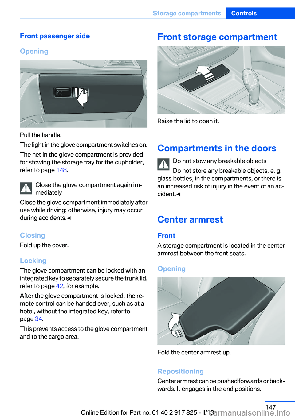
Opening
Pull the handle.
The light in the glove compartment switches on.
The net in the glove compartment is provided
for stowing the storage tray for the cupholder,
refer to page 148.
Close the glove compartment again im‐
mediately
Close the glove compartment immediately after
use while driving; otherwise, injury may occur
during accidents.◀
Closing
Fold up the cover.
Locking
The glove compartment can be locked with an
integrated key to separately secure the trunk lid,
refer to page 42, for example.
After the glove compartment is locked, the re‐
mote control can be handed over, such as at a
hotel, without the integrated key, refer to
page 34.
This prevents access to the glove compartment
and to the cargo area.
Front storage compartment
Raise the lid to open it.
Compartments in the doors Do not stow any breakable objects
Do not store any breakable objects, e. g.
glass bottles, in the compartments, or there is
an increased risk of injury in the event of an ac‐
cident.◀
Center armrest
Front
A storage compartment is located in the center
armrest between the front seats.
Opening
Fold the center armrest up.
Repositioning
Center armrest can be pushed forwards or back‐
wards. It engages in the end positions.
Seite 147Storage compartmentsControls147
Online Edition for Part no. 01 40 2 917 825 - II/13