2013 BMW 750I tow
[x] Cancel search: towPage 113 of 243

Switching on/off
Switching on automatically
The system is automatically active every time
the engine is started using the Start/Stop but‐
ton.
Switching off
The system is only switched off until the next
time the engine is started with the Start/Stop
button.
Press the button
The LED goes out.
Setting the warning time
The warning time can be set via iDrive.
These settings have no effect on the time of the
warning when the system prompts the driver to
intervene or brake.1."Settings"2."Intelligent Safety"3."Collision Warning System"4.Activate the desired warning time on the
Control Display.
The selected channel is stored for the remote
control currently in use.
Display
Warning stages
Prewarning
This warning is issued, for example, when there
is the impending danger of a collision or the dis‐
tance to the vehicle ahead is too small.
Acute warning with braking function
Warning of the imminent danger of a collision
when the vehicle approaches another object at
a relatively high differential speed.
The acute warning prompts the driver to inter‐
vene and, if there is the danger of a collision, is
accompanied by a braking intervention.
The braking intervention is executed with lim‐
ited braking force and for a brief period only. The
intervention will not bring the vehicle to a com‐
plete standstill.
The braking intervention is executed only if DSC
Dynamic Stability Control is switched on.
Adapting your speed and driving style
The acute warning does not relieve the
driver of the responsibility to adapt his or her
driving speed and style to the traffic condi‐
tions.◀
The braking intervention can be interrupted by
pressing on the accelerator or by actively mov‐
ing the steering wheel.
When towing or tow-starting the vehicle, switch
off the collision warning with braking function to
prevent undesired interventions.
The braking function is deactivated if the DSC
Dynamic Stability Control or DTC Dynamic
Traction Control is deactivated.
Display in the instrument cluster
The collision warning can be issued in the in‐
strument cluster, in the Head-up Display, and
acoustically.
Warning stagesSymbolMeasureThe vehicle lights up red: prewarn‐
ing.
Increase distance.The vehicle flashes red and an
acoustic signal sounds: acute warn‐
ing.
You are requested to intervene by
braking or making an evasive maneu‐
ver.Seite 113SafetyControls113
Online Edition for Part no. 01 40 2 916 693 - X/12
Page 116 of 243

Press the button.
The LED goes out.
Switching on heat image additionally
The heat image from the Night Vision camera
can also be displayed on the Control Display.
This function has no effect on people detection.
Press the button.
The image from the camera is displayed on the
Control Display.
Adjustments via the iDrive
With Night Vision switched on:1.Press the controller.2.Select the desired menu item.▷ "Brightness"▷ "Contrast"
Display
Warning of people in danger
If a collision with a person detected in this way
is imminent, a warning symbol appears on the
instrument cluster and in the Head-up Display.
Although both the shape and the heat radiation
are analyzed, false warnings cannot be ruled out.
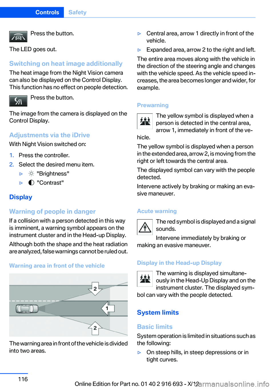
Warning area in front of the vehicle
The warning area in front of the vehicle is divided
into two areas.
▷Central area, arrow 1 directly in front of the
vehicle.▷Expanded area, arrow 2 to the right and left.
The entire area moves along with the vehicle in
the direction of the steering angle and changes
with the vehicle speed. As the vehicle speed in‐
creases, the area becomes longer and wider, for
example.
Prewarning The yellow symbol is displayed when a
person is detected in the central area,
arrow 1, immediately in front of the ve‐
hicle.
The yellow symbol is displayed when a person
in the extended area, arrow 2, is moving from the
right or left towards the central area.
The displayed symbol can vary with the people
detected.
Intervene actively by braking or making an eva‐
sive maneuver.
Acute warning The red symbol is displayed and a signal
sounds.
Intervene immediately by braking or
making an evasive maneuver.
Display in the Head-up Display The warning is displayed simultane‐
ously in the Head-Up Display and on the
instrument cluster. The displayed sym‐
bol can vary with the people detected.
System limits
Basic limits
System operation is limited in situations such as
the following:
▷On steep hills, in steep depressions or in
tight curves.Seite 116ControlsSafety116
Online Edition for Part no. 01 40 2 916 693 - X/12
Page 118 of 243

▷Off: the LED goes out.
The state is stored for the remote control cur‐
rently in use.
Display in the instrument cluster
▷Lines: system is activated.▷Arrows: at least one lane marking
was detected and warnings can be
issued.
Display in the instrument display
▷Symbol red: system is activated.▷Symbol green: at least one lane
marking was detected and warnings
can be issued.
Issued warning
If you leave the lane and if a lane marking has
been detected, the steering wheel begins vi‐
brating.
If the turn signal is set before changing the lane,
a warning is not issued.
End of warning
The warning ends:
▷Automatically after approx. 3 seconds.▷When returning to your own lane.▷When braking hard.▷When using the turn signal.
System limits
The system may not be fully functional in the
following situations:
▷In heavy fog, rain or snowfall.▷In the event of worn, poorly visible, merging,
diverging, or multiple lane markings such as
in construction areas.▷When lane markings are covered in snow,
ice, dirt or water.▷In tight curves or on narrow lanes.▷When the lane markings are covered by ob‐
jects.▷When driving very close to the vehicle in
front of you.▷When driving toward bright lights.▷When the windshield behind the interior
rearview mirror is fogged over, dirty or cov‐
ered with stickers, etc.▷During calibration of the camera immedi‐
ately after vehicle shipment.
Active Blind Spot Detection
The concept
Two radar sensors below the rear bumper mon‐
itor the area behind and next to the vehicle at
speeds above approx. 30 mph/50 km/h.
The system indicates whether there are vehicles
in the blind spot, arrow 1, or approaching from
behind on the adjacent lane, arrow 2.
The lamp in the exterior mirror housing lights up
dimly.
Before you change lanes after setting the turn
signal, the system issues a warning in the situa‐
tions described above.
The lamp in the housing of the exterior mirror
flashes and the steering wheel vibrates.
Seite 118ControlsSafety118
Online Edition for Part no. 01 40 2 916 693 - X/12
Page 141 of 243

The range of the sensors is represented in col‐
ors: red, green and yellow.
If the backup camera image was selected last, it
again appears on the display. To switch to PDC:1. "Rear view camera" Select the symbol
on the Control Display.2.Press the controller.
The setting is stored for the remote control cur‐
rently in use.
System limits
Limits of ultrasonic measurement
The detection of objects can reach the physical
limits of ultrasonic measurement, e.g.:
▷With tow bars and trailer hitches.▷With thin or wedge-shaped objects.▷With low objects.▷With objects with corners and sharp edges.
Low objects already displayed, e.g., curbs, can
move into the blind area of the sensors before or
after a continuous tone sounds.
High, protruding objects such as ledges may not
be detected.
False warnings
PDC may issue a warning under the following
conditions even though there is no obstacle
within the detection range:
▷In heavy rain.▷When sensors are very dirty or covered in
ice.▷When sensors are covered in snow.▷On rough road surfaces.▷In large buildings with right angles and
smooth walls, e.g., in underground garages.▷In heavy exhaust.▷Due to other ultrasound sources, e.g.,
sweeping machines, high pressure steam
cleaners or neon lights.Malfunction
A Check Control message is displayed.
The range of the sensors is shown as a shaded
area on the Control Display.
PDC has failed. Have the system checked.
To ensure full operability:▷Keep the sensors clean and free of ice.▷When using high-pressure washers, do not
spray the sensors for long periods and main‐
tain a distance of at least 12 in/30 cm.
Surround View
The concept
Surround View includes the following systems:
▷Backup camera, refer to page 141.▷Side View, refer to page 144.▷Top View, refer to page 145.
It assists the driver when parking, maneuvering
and on blind driveways and intersections.
Backup camera
The concept
The backup camera provides assistance in park‐
ing and maneuvering backwards. The area be‐
hind the vehicle is shown on the Control Display.
Notes Check the traffic situation as well
Check the traffic situation around the ve‐
hicle with your own eyes. Otherwise, an accident
could result from road users or objects located
outside the picture area of the backup camera. ◀
Seite 141Driving comfortControls141
Online Edition for Part no. 01 40 2 916 693 - X/12
Page 150 of 243

The status of the parking space search is in‐
dicated on the Control Display.2.Follow the instructions on the Control Dis‐
play.
To achieve the best possible parking posi‐
tion, wait for the automatic steering wheel
movement after the gear change when the
vehicle is stationary.
The end of the parking procedure is indi‐
cated on the Control Display.3.Adjust the parking position yourself if nec‐
essary.
Interrupting manually
The parking assistant can be interrupted at any
time:
▷ " Parking Assistant" Select the symbol on
the Control Display.▷Press the button.
Interrupting automatically
The system is interrupted automatically in the
following situations:
▷If the driver grasps the steering wheel or if
he takes over steering.▷If a gear is selected that does not match the
instruction on the Control Display.▷If a turn signal is activated in the opposite
direction to the desired side for parking.▷If the vehicle speed exceeds approx.
6 mph/10 km/h.▷On snow-covered or slippery road surfaces
if necessary.▷If doors are open.▷If the Park Distance Control PDC displays
clearances that are too small.▷If a maximum number of parking attempts or
the time taken for parking is exceeded.
A Check Control message is displayed.
Continuing
An interrupted parking procedure can be con‐
tinued if necessary.
Follow the instructions on the Control Display to
do this.
System limits
No parking assistance
The parking assistant does not offer assistance
in the following situations:▷In tight curves.
Functional limitations
The system may not be fully functional in the
following situations:
▷When sensors are dirty or iced over.▷In heavy fog, rain or snowfall.▷On bumpy road surfaces such as gravel
roads.▷When leaves or snow has collected in the
parking space.
Limits of ultrasonic measurement
The detection of objects can reach the physical
limits of ultrasonic measurement, e.g. in the fol‐
lowing circumstances:
▷With tow bars and trailer hitches.▷With thin or wedge-shaped objects.▷With elevated, protruding objects such as
ledges or cargo.▷With objects with corners and sharp edges.▷With objects with a fine surface structure,
such as fences.
Low objects already displayed, e.g., curbs, can
move into the blind area of the sensors before or
after a continuous tone sounds.
High, protruding objects such as ledges may not
be detected.
The parking assistant may identify parking
spaces that are not suitable for parking.
Seite 150ControlsDriving comfort150
Online Edition for Part no. 01 40 2 916 693 - X/12
Page 157 of 243

is shown on the display of the automatic cli‐
mate control.
The interior temperature, air volume and air dis‐
tribution can be adjusted with the ignition
switched on.
Switching off
At the lowest fan speed, press the left side of the
button on the driver's side.
on the display of the automatic climate control
goes out.
Switching the system on/off
Switching off
▷Complete system: Press and hold the left button on
the driver's side until the control
clicks off.▷On the front passenger side:
Press and hold the left button on
the front passenger side.
Switching on
Press any button except:
▷ALL program.▷Rear window defroster.▷Left side of Air volume button.▷Seat heating.▷Seat ventilation.
Microfilter/activated-charcoal filter
The microfilter removes dust and pollen from
the incoming air.
The activated-charcoal filter removes gaseous
pollutants from the outside air that enters the
vehicle.
This combined filter should be replaced during
scheduled maintenance, refer to page 208, of
your vehicle.
Ventilation
Front ventilation▷Thumbwheels to vary the temperature, ar‐
row 1.
Toward blue: colder.
Toward red: warmer.▷Lever for changing the air flow direction, ar‐
row 2.▷Thumbwheels for opening and closing the
vents continuously, arrows 3.
Ventilation levels
▷Draft-free ventilation:
Thumbwheel, arrow 3, in level
: the air
current is fanned out.
▷Maximum air flow:
Thumbwheel, arrow 3, in level
: the air is
partially fanned out and partially bundled.
This maximizes the air supply.
▷Direct ventilation:
Thumbwheel, arrow 3, in level
: the air is
bundled and can be directed to a specific
point.
Adjusting the ventilation
▷Ventilation for cooling:
Adjust the vent to direct the air in your di‐
rection, such as if the vehicle interior is hot
from the sun.▷Draft-free ventilation:
Adjust the vent to let the air flow past you.Seite 157Climate controlControls157
Online Edition for Part no. 01 40 2 916 693 - X/12
Page 158 of 243

Ventilation in rear, center▷Thumbwheels to vary the temperature, ar‐
row 1.
Toward blue: colder.
Toward red: warmer.▷Lever for changing the air flow direction, ar‐
row 2.▷Thumbwheels for continuous opening and
closing of the vents, arrow 3.
Lateral ventilation
▷Thumbwheel for continuous opening and
closing of the vents, arrow 1.▷Lever for changing the air flow direction, ar‐
row 2.Rear automatic climate
control
At a glance1Temperature2AUTO program3Vent settings4Air flow, AUTO intensity5Display6Maximum cooling7Seat heating 538Active seat ventilation 54
Switching the rear automatic climate
control on/off
1."Settings"2."Climate"3."Rear climate control"
The rear automatic climate control is not opera‐
tional if the automatic climate control is
switched off or if the function for defrosting or
defogging the windows is active.
AUTO program Press the button.
Air flow, air distribution, and tempera‐
ture are controlled automatically:
Depending on the selected temperature, AUTO
intensity, and outside influences, the air is di‐
rected to the upper body and into the footwell.
Seite 158ControlsClimate control158
Online Edition for Part no. 01 40 2 916 693 - X/12
Page 168 of 243

Storage compartmentsVehicle equipment
All standard, country-specific and optional
equipment that is offered in the model series is
described in this chapter. Therefore, equipment
is also described that is not available in a vehicle,
e. g., because of the selected optional equip‐
ment or country variant. This also applies for
safety-related functions and systems.
Notes No loose objects in the passenger com‐
partment
Do not stow any objects in the passenger com‐
partment without securing them; otherwise,
they may present a danger to occupants for in‐
stance during braking and avoidance maneu‐
vers.◀
Do not place anti-slip mats on the dash‐
board
Do not place anti-slip mats on the dashboard.
The mat materials could damage the dash‐
board.◀
Storage compartments
The following storage compartments are avail‐
able in the vehicle interior:▷Glove compartment on the driver's and front
passenger side, refer to page 168.▷Storage compartment in the center armrest,
refer to page 169, in the front and rear.▷Compartments in the doors.▷Pockets on the backrests of the front seats.▷Net in the front passenger footwell.Glove compartment
Front passenger side
Opening
Pull the handle.
The light in the glove compartment switches on.
Close the glove compartment again im‐
mediately
Close the glove compartment immediately after
use while driving; otherwise, injury may occur
during accidents.◀
Closing
Fold up the cover.
Opening the top cover
Press the button.
The top cover opens automatically.
Seite 168ControlsStorage compartments168
Online Edition for Part no. 01 40 2 916 693 - X/12