2013 BMW 740LI XDRIVE night vision
[x] Cancel search: night visionPage 12 of 243
CockpitVehicle equipment
All standard, country-specific and optional
equipment that is offered in the model series is
described in this chapter. Therefore, equipmentis also described that is not available in a vehicle,
e. g., because of the selected optional equip‐
ment or country variant. This also applies for
safety-related functions and systems.
All around the steering wheel
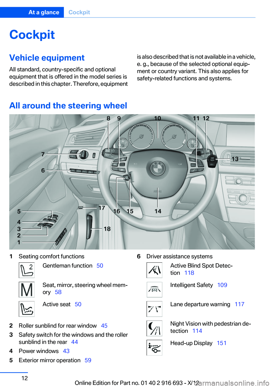
1Seating comfort functionsGentleman function 50Seat, mirror, steering wheel mem‐
ory 58Active seat 502Roller sunblind for rear window 453Safety switch for the windows and the roller
sunblind in the rear 444Power windows 435Exterior mirror operation 596Driver assistance systemsActive Blind Spot Detec‐
tion 118Intelligent Safety 109Lane departure warning 117Night Vision with pedestrian de‐
tection 114Head-up Display 151Seite 12At a glanceCockpit12
Online Edition for Part no. 01 40 2 916 693 - X/12
Page 33 of 243
4.Open "Guest".5.Adjust the settings.
Note: the guest profile cannot be renamed.
Display profile list during start
The profile list can be displayed during each
start for selecting the desired profile.
1."Settings"2."Profiles"3.Open "Options".4."Display user list at startup"
Personal Profile settings
The following functions and settings can be
stored in a profile.
More information on the settings can be found
under:
▷Active Cruise Control: collision warning.▷Collision warning: warning time, last setting
on/off.▷Exterior mirror position.▷CD/Multimedia: audio source listened to
last.▷Driving Dynamics Control: sport program.▷Driver's seat position: automatic retrieval af‐
ter unlocking.▷Programmable memory buttons: assign‐
ment.▷Head-up Display: selection, brightness, po‐
sition and rotation of the display.▷Headlamp courtesy delay feature: time set‐
ting.▷Tone: tone settings.▷Automatic climate control: settings.▷Steering wheel position.▷Navigation: map views, route criteria, voice
output on/off.▷Night Vision with pedestrian detection: se‐
lection of functions and type of display.▷Park Distance Control PDC: adjusting the
signal tone volume.▷Radio: stored stations, station listened to
last, special settings.▷Backup camera: selection of functions and
type of display.▷Side View: selection of the display type.▷Language on the Control Display.▷Lane departure warning: last setting, on/off.▷Active Blind Spot Detection: last setting, on/
off.▷Daytime running lights: current setting.▷Triple turn signal activation.▷Locking the vehicle: after a brief period or
after starting to drive.
Central locking system
The concept
The central locking system becomes active
when the driver's door is closed.
The system simultaneously engages and re‐
leases the locks on the following:
▷Doors.▷Trunk lid.▷Fuel filler flap.
Operating from the outside
▷Via the remote control.▷Via the driver's door lock.▷Via the door handles.▷Via the button in the trunk lid.
The following takes place simultaneously when
locking/unlocking the vehicle via the remote
control:
▷Depending on how the vehicle is equipped,
the theft protection is activated/deactivated.
Theft protection prevents the doors from
being unlocked using the lock buttons or the
door opener.Seite 33Opening and closingControls33
Online Edition for Part no. 01 40 2 916 693 - X/12
Page 109 of 243
MalfunctionThe yellow warning lamp flashes and
then lights up continuously. A Check
Control message is displayed. No flat
tire can be detected.
Display in the following situations:▷A wheel without TPM electronics is fitted:
have the service center check it if necessary.▷Malfunction: have the system checked by
your service center.▷TPM could not be fully reset. Reset the sys‐
tem again.▷Disturbance by systems or devices with the
same radio frequency: after leaving the area
of the disturbance, the system automatically
becomes active again.
Declaration according to NHTSA/
FMVSS 138 Tire Pressure Monitoring
System
Each tire, including the spare (if provided)
should be checked monthly when cold and in‐
flated to the inflation pressure recommended by
the vehicle manufacturer on the vehicle placard
or tire inflation pressure label. (If your vehicle has
tires of a different size than the size indicated on
the vehicle placard or tire inflation pressure la‐
bel, you should determine the proper tire infla‐
tion pressure for those tires.) As an added safety
feature, your vehicle has been equipped with a
tire pressure monitoring system (TPMS) that il‐
luminates a low tire pressure telltale when one
or more of your tires is significantly under-in‐
flated. Accordingly, when the low tire pressure
telltale illuminates, you should stop and check
your tires as soon as possible, and inflate them
to the proper pressure. Driving on a significantly
under-inflated tire causes the tire to overheat
and can lead to tire failure. Under-inflation also
reduces fuel efficiency and tire tread life, and
may affect the vehicle's handling and stopping
ability. Please note that the TPMS is not a sub‐
stitute for proper tire maintenance, and it is the
driver's responsibility to maintain correct tire
pressure, even if under-inflation has not reached
the level to trigger illumination of the TPMS low
tire pressure telltale. Your vehicle has also been
equipped with a TPMS malfunction indicator to
indicate when the system is not operating prop‐
erly. The TPMS malfunction indicator is com‐
bined with the low tire pressure telltale. When
the system detects a malfunction, the telltale will
flash for approximately one minute and then re‐
main continuously illuminated. This sequence
will continue upon subsequent vehicle start-ups
as long as the malfunction exists. When the mal‐
function indicator is illuminated, the system may
not be able to detect or signal low tire pressure
as intended. TPMS malfunctions may occur for
a variety of reasons, including the installation of
replacement or alternate tires or wheels on the
vehicle that prevent the TPMS from functioning
properly. Always check the TPMS malfunction
telltale after replacing one or more tires or
wheels on your vehicle to ensure that the re‐
placement or alternate tires and wheels allow
the TPMS to continue to function properly.
Intelligent Safety
The concept
Depending on how the vehicle is equipped, In‐
telligent Safety consists of one or more of the
following systems, which can help to avoid an
imminent collision. These systems are switched
on automatically every time the engine is started
using the Start/Stop button:▷Collision warning with braking function, re‐
fer to page 112▷Night Vision with pedestrian detection, refer
to page 114.
Note
Personal responsibility
The system does not serve as a substitute
for the driver's personal judgment of the traffic
situation.
Seite 109SafetyControls109
Online Edition for Part no. 01 40 2 916 693 - X/12
Page 114 of 243
Adapting your speed and driving style
The display does not relieve the driver of
the responsibility to adapt his or her driving
speed and style to the traffic conditions.◀
System limits Be alert
Due to system limitations, warnings may
be not be issued at all, or may be issued late or
improperly. Therefore, always be alert and ready
to intervene; otherwise, there is the danger of an
accident occurring.◀
Detection range
The detection capacity of the radar sensor and
the collision warning has limitations.
This may result in the warning not being issued
or being issued late.
For example, the following situations may not be
detected:▷Slow moving vehicles when you approach
them at high speed.▷Vehicles that suddenly swerve in front of you
or sharply decelerating vehicles.▷Vehicles with an unusual rear appearance.▷Two-wheeled vehicles ahead of you.▷Pedestrians.
Functional limitations
The system may not be fully functional in the
following situations:
▷In heavy fog, rain, sprayed water or snowfall.▷In tight curves.▷If the radar sensor is dirty or obscured.
Prewarning sensitivity
Depending on the set prewarning time, this may
result in increased false warnings.
Night Vision with pedestrian
detection
The concept
Night Vision with pedestrian detection is a night
vision system.
An infrared camera records the area in front of
the vehicle and issues a warning if it detects pe‐
destrians on the street. Warm objects that are
similar in shape to human beings are detected
by the system. If necessary, the heat image can
be displayed on the Control Display.
Depending on how the vehicle is equipped, peo‐
ple will be illuminated by a Light Spot or Dynamic
Light Spot so that they are more easibly visible.
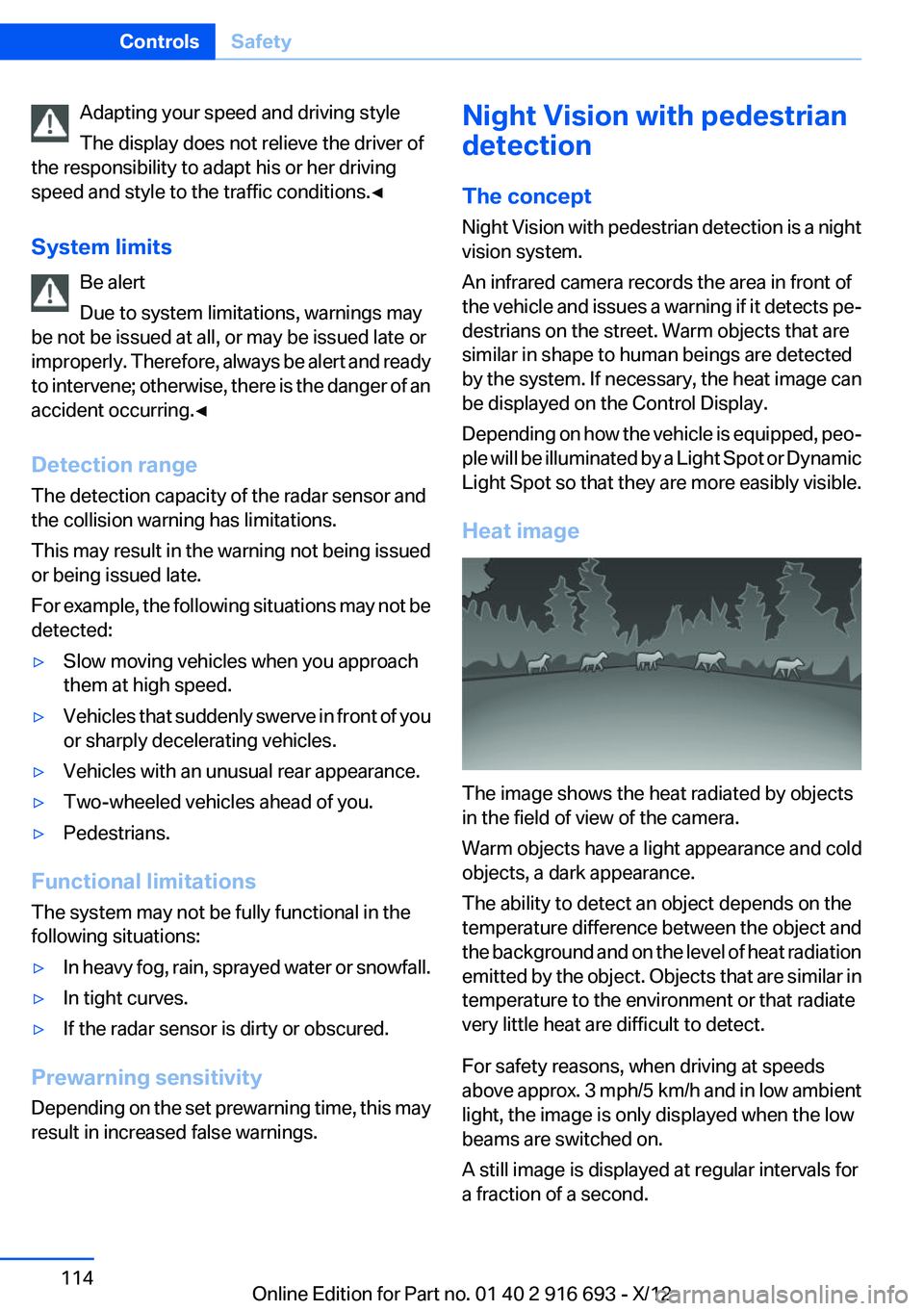
Heat image
The image shows the heat radiated by objects
in the field of view of the camera.
Warm objects have a light appearance and cold
objects, a dark appearance.
The ability to detect an object depends on the
temperature difference between the object and
the background and on the level of heat radiation
emitted by the object. Objects that are similar in
temperature to the environment or that radiate
very little heat are difficult to detect.
For safety reasons, when driving at speeds
above approx. 3 mph/5 km/h and in low ambient
light, the image is only displayed when the low
beams are switched on.
A still image is displayed at regular intervals for
a fraction of a second.
Seite 114ControlsSafety114
Online Edition for Part no. 01 40 2 916 693 - X/12
Page 115 of 243
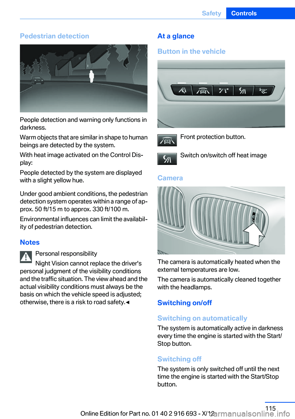
Pedestrian detection
People detection and warning only functions in
darkness.
Warm objects that are similar in shape to human
beings are detected by the system.
With heat image activated on the Control Dis‐
play:
People detected by the system are displayed
with a slight yellow hue.
Under good ambient conditions, the pedestrian
detection system operates within a range of ap‐
prox. 50 ft/15 m to approx. 330 ft/100 m.
Environmental influences can limit the availabil‐
ity of pedestrian detection.
Notes Personal responsibility
Night Vision cannot replace the driver's
personal judgment of the visibility conditions
and the traffic situation. The view ahead and the
actual visibility conditions must always be the
basis on which the vehicle speed is adjusted;
otherwise, there is a risk to road safety.◀
At a glance
Button in the vehicle
Front protection button.
Switch on/switch off heat image
Camera
The camera is automatically heated when the
external temperatures are low.
The camera is automatically cleaned together
with the headlamps.
Switching on/off
Switching on automatically
The system is automatically active in darkness
every time the engine is started with the Start/
Stop button.
Switching off
The system is only switched off until the next
time the engine is started with the Start/Stop
button.
Seite 115SafetyControls115
Online Edition for Part no. 01 40 2 916 693 - X/12
Page 116 of 243
Press the button.
The LED goes out.
Switching on heat image additionally
The heat image from the Night Vision camera
can also be displayed on the Control Display.
This function has no effect on people detection.
Press the button.
The image from the camera is displayed on the
Control Display.
Adjustments via the iDrive
With Night Vision switched on:1.Press the controller.2.Select the desired menu item.▷ "Brightness"▷ "Contrast"
Display
Warning of people in danger
If a collision with a person detected in this way
is imminent, a warning symbol appears on the
instrument cluster and in the Head-up Display.
Although both the shape and the heat radiation
are analyzed, false warnings cannot be ruled out.
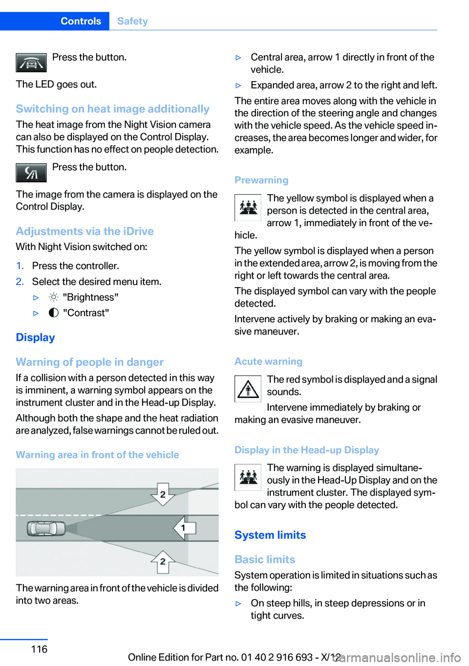
Warning area in front of the vehicle
The warning area in front of the vehicle is divided
into two areas.
▷Central area, arrow 1 directly in front of the
vehicle.▷Expanded area, arrow 2 to the right and left.
The entire area moves along with the vehicle in
the direction of the steering angle and changes
with the vehicle speed. As the vehicle speed in‐
creases, the area becomes longer and wider, for
example.
Prewarning The yellow symbol is displayed when a
person is detected in the central area,
arrow 1, immediately in front of the ve‐
hicle.
The yellow symbol is displayed when a person
in the extended area, arrow 2, is moving from the
right or left towards the central area.
The displayed symbol can vary with the people
detected.
Intervene actively by braking or making an eva‐
sive maneuver.
Acute warning The red symbol is displayed and a signal
sounds.
Intervene immediately by braking or
making an evasive maneuver.
Display in the Head-up Display The warning is displayed simultane‐
ously in the Head-Up Display and on the
instrument cluster. The displayed sym‐
bol can vary with the people detected.
System limits
Basic limits
System operation is limited in situations such as
the following:
▷On steep hills, in steep depressions or in
tight curves.Seite 116ControlsSafety116
Online Edition for Part no. 01 40 2 916 693 - X/12
Page 117 of 243
▷When the camera is dirty or the protective
glass is damaged.▷In heavy fog, rain or snowfall.▷At very high external temperatures.
Limits of pedestrian detection
Animals are not detected by the pedestrian de‐
tection function, even if they are clearly visible in
the image.
Limited pedestrian detection:
▷People who are fully or partially covered, es‐
pecially when their heads are covered.▷People who are not in an upright position,
e.g., lying down.▷Cyclists on unconventional bicycles (e.g.,
recumbent bicycles).▷After physical damage to the system, e.g.,
after an accident.
No display on the rear screen
The image from Night Vision with people detec‐
tion cannot be displayed on the rear screen.
Lane departure warning
The concept
Starting at a specific speed, this system alerts
you when the vehicle on streets with lane mark‐
ings is about to leave the lane. Depending on the
country-specific version of the vehicle, the
speed is between 35 mph/55 km/h and
45 mph/70 km/h. When switching on the system
below this speed, a message appears in the in‐
strument cluster.
The steering wheel begins vibrating gently in the
event of warnings. The time of the warning may
vary depending on the current driving situation.
The system does not provide a warning if the
turn signal is set before leaving the lane.
Notes
Personal responsibility
The system cannot serve as a substitute
for the driver's personal judgment of the course
of the road and the traffic situation.
In the event of a warning, do not jerk the steering
wheel, as you may lose control of the vehicle.◀
At a glance
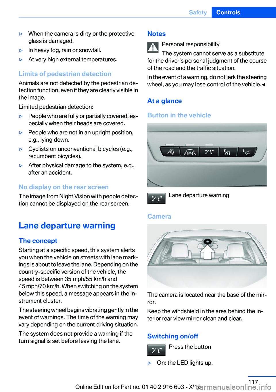
Button in the vehicle
Lane departure warning
Camera
The camera is located near the base of the mir‐
ror.
Keep the windshield in the area behind the in‐
terior rear view mirror clean and clear.
Switching on/off Press the button
▷On: the LED lights up.Seite 117SafetyControls117
Online Edition for Part no. 01 40 2 916 693 - X/12
Page 234 of 243
Condensation under the vehi‐cle 176
Condition Based Service CBS 208
Configure driving mode 129
Confirmation signal 35
ConnectedDrive, see user's manual for Navigation, Enter‐
tainment and Communica‐
tion
Control Display 16
Control Display, settings 93
Controller 16
Control systems, driving sta‐ bility 123
Convenient opening 34
Coolant 207
Coolant temperature 86
Cooler 165
Cooling function 156
Cooling, maximum 155
Cooling system 207
Corrosion on brake discs 176
Cruise control 137
Cruise control, active with Stop & Go 131
Cruising range 87
Cupholder 170
Curb weight 229
Current fuel consumption 87
D
Damage, tires 198
Damping control, dy‐ namic 126
Data, technical 228
Date 87
Daytime running lights 96
Defrosting, refer to Windows, defrosting 155
Dehumidifying, air 156
Destination distance 91
Digital clock 86
Dimensions 228
Dimmable exterior mirrors 60 Dimmable interior rearview
mirror 60
Direction indicator, refer to Turn signals 73
Display in windshield 151
Display lighting, refer to Instru‐ ment lighting 98
Displays 79, 80
Displays, cleaning 225
Disposal, vehicle battery 216
Distance control, refer to PDC 139
Distance information 152
Distance, selecting for ACC 133
Distance to destination 91
Divided screen view, split screen 20
Door lock, refer to Remote control 30
Doors, Automatic Soft Clos‐ ing 37
Downhill control 125
Drive-off assistant 123
Drive-off assistant, refer to DSC 123
Driving Dynamics Control 127
Driving instructions, breaking in 174
Driving mode 127
Driving notes, general 174
Driving stability control sys‐ tems 123
Driving tips 174
DSC Dynamic Stability Con‐ trol 123
DTC driving dynamics 124
DTC Dynamic Traction Con‐ trol 124
Dynamic Damping Con‐ trol 126
Dynamic Drive 126
Dynamic Light Spot 213
Dynamic Light Spot, refer to Night Vision 114 Dynamic Stability Control
DSC 123
Dynamic Traction Control DTC 124
E
ECO PRO 181
ECO PRO, bonus range 182
ECO PRO display 181
ECO PRO driving mode 181
ECO PRO mode 181
ECO PRO Tip - driving instruc‐ tion 183
EfficientDynamics 183
Electronic displays, instru‐ ment cluster 80
Electronic Stability Program ESP, refer to DSC 123
Emergency detection, remote control 31
Emergency release, door lock 36
Emergency release, fuel filler flap 188
Emergency release, parking brake 70
Emergency Request 217
Emergency service, refer to Roadside Assistance 218
Emergency start function, en‐ gine start 31
Emergency unlocking, trunk lid 40
Energy Control 87
Energy recovery 87
Engine, automatic Start/Stop function 68
Engine, automatic switch- off 68
Engine compartment 202
Engine compartment, working in 202
Engine coolant 207
Engine idling when driving, coasting 184 Seite 234ReferenceEverything from A to Z234
Online Edition for Part no. 01 40 2 916 693 - X/12