2013 BMW 740LI XDRIVE trunk
[x] Cancel search: trunkPage 174 of 243
Things to remember when drivingVehicle equipment
All standard, country-specific and optional
equipment that is offered in the model series is
described in this chapter. Therefore, equipment
is also described that is not available in a vehicle,
e. g., because of the selected optional equip‐
ment or country variant. This also applies for
safety-related functions and systems.
Breaking-in period
General information
Moving parts need to be broken in to adjust to
each other.
The following instructions will help achieve a
long vehicle life and good economy.
Engine and differential
Always obey the official speed limit.
Up to 1,200 miles/2,000 km
Do not exceed the maximum engine and road
speed:▷For gasoline engine, 4,500 rpm and
100 mph/160 km/h.
Avoid full load or kick-down under all circum‐
stances.
From 1,200 miles/2,000 km
The engine and vehicle speed can gradually be
increased.
Tires
Due to technical factors associated with their
manufacture, tires do not achieve their full trac‐
tion potential until after an initial breaking-in pe‐
riod.
Drive conservatively for the first
200 miles/300 km.
Brake system
Brakes require an initial break-in period of ap‐
prox. 300 miles/500 km to achieve optimized
contact and wear patterns between brake discs
and brake pads. Drive moderately during this
break-in period.
Following part replacement
The same breaking in procedures should be ob‐
served if any of the components mentioned
above have to be renewed in the course of the
vehicle's operating life.
General driving notes
Closing the trunk lid Drive with the trunk lid closed
Only drive with the tailgate closed; other‐
wise, in the event of an accident or braking or
evasive maneuvers, passengers or other road
users may be injured or the vehicle may be dam‐
aged. In addition, exhaust fumes may enter the
passenger compartment.◀
If driving with the tailgate open cannot be
avoided:▷Close all windows and the glass sunroof.▷Greatly increase the blower speed.▷Drive moderately.
Hot exhaust system
Hot exhaust system
High temperatures are generated in the
exhaust system.
Do not remove the heat shields installed and
never apply undercoating to them. When driv‐
ing, standing at idle and while parking, take care
to avoid possible contact between the hot ex‐
haust system and any highly flammable materi‐
Seite 174Driving tipsThings to remember when driving174
Online Edition for Part no. 01 40 2 916 693 - X/12
Page 177 of 243
LoadingVehicle equipment
All standard, country-specific and optional
equipment that is offered in the model series is
described in this chapter. Therefore, equipment
is also described that is not available in a vehicle,
e. g., because of the selected optional equip‐
ment or country variant. This also applies for
safety-related functions and systems.
Hints Overloading the vehicle
To avoid exceeding the approved carrying
capacity of the tires, never overload the vehicle.
Overloading can lead to overheating and in‐
creases the rate at which damage develops in‐
side the tires. This could result in a sudden loss
of tire inflation pressure.◀
No fluids in the trunk
Make sure that fluids do not leak into the
trunk; otherwise, the vehicle may be damaged. ◀
Determining the load limit1.Locate the following statement on your ve‐
hicle’s placard:▷The combined weight of occupants and
cargo should never exceed XXX kg or
YYY lbs. Otherwise, damage to the ve‐hicle and unstable driving situations may
result.2.Determine the combined weight of the
driver and passengers that will be riding in
your vehicle.3.Subtract the combined weight of the driver
and passengers from XXX kilograms or YYY
pounds.4.The resulting figure equals the available
amount of cargo and luggage load capacity.
For example, if the YYY amount equals
1,000 lbs and there will be four 150 lbs pas‐
sengers in your vehicle, the amount of avail‐
able cargo and luggage load capacity is
400 lbs: 1,000 lbs minus 600 lbs = 400 lbs.5.Determine the combined weight of luggage
and cargo being loaded on the vehicle. That
weight may not safely exceed the available
cargo and luggage load capacity calculated
in Step 4.
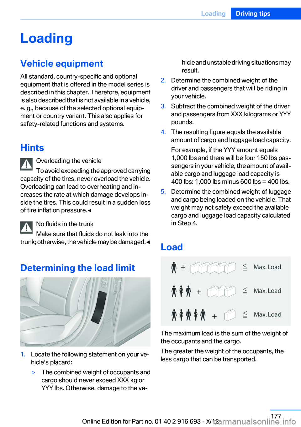
Load
The maximum load is the sum of the weight of
the occupants and the cargo.
The greater the weight of the occupants, the
less cargo that can be transported.
Seite 177LoadingDriving tips177
Online Edition for Part no. 01 40 2 916 693 - X/12
Page 179 of 243
Loading
Because roof racks raise the vehicle's center of
gravity when loaded, they have a major effect on
vehicle handling and steering response.
Therefore, note the following when loading and
driving:▷Do not exceed the approved roof/axle loads
and the approved gross vehicle weight.▷Distribute the roof load uniformly.▷The roof load should not be too large in area.▷Always place the heaviest pieces on the bot‐
tom.▷Secure the roof luggage firmly, e.g., tie with
ratchet straps.▷Do not let objects project into the opening
path of the trunk lid.▷Drive cautiously and avoid sudden acceler‐
ation and braking maneuvers. Take corners
gently.Seite 179LoadingDriving tips179
Online Edition for Part no. 01 40 2 916 693 - X/12
Page 210 of 243
Replacing componentsVehicle equipment
All standard, country-specific and optional
equipment that is offered in the model series is
described in this chapter. Therefore, equipment
is also described that is not available in a vehicle,
e. g., because of the selected optional equip‐
ment or country variant. This also applies for
safety-related functions and systems.
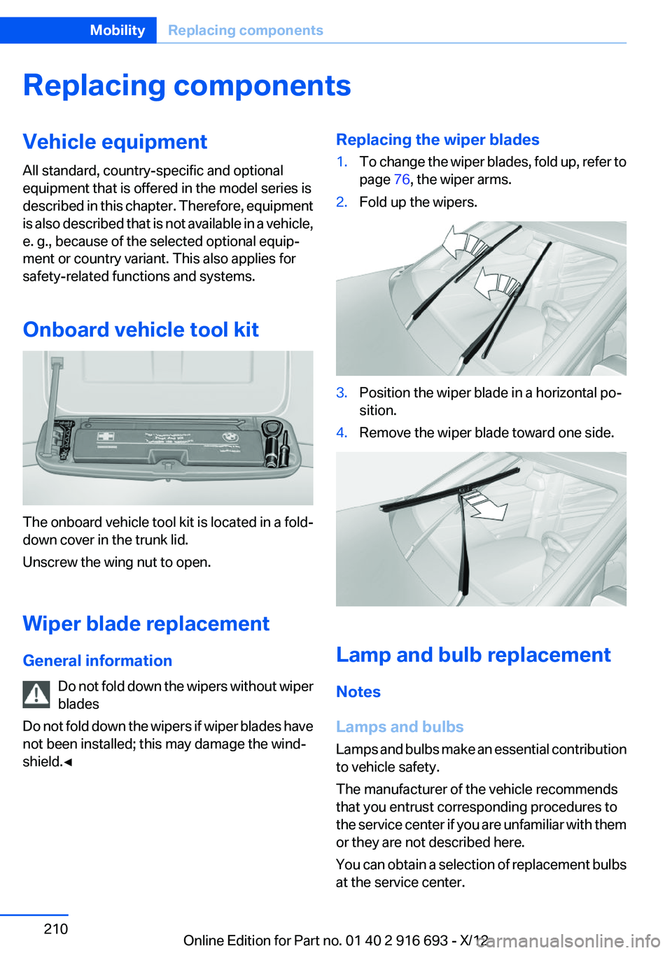
Onboard vehicle tool kit
The onboard vehicle tool kit is located in a fold-
down cover in the trunk lid.
Unscrew the wing nut to open.
Wiper blade replacement
General information Do not fold down the wipers without wiper
blades
Do not fold down the wipers if wiper blades have
not been installed; this may damage the wind‐
shield.◀
Replacing the wiper blades1.To change the wiper blades, fold up, refer to
page 76, the wiper arms.2.Fold up the wipers.3.Position the wiper blade in a horizontal po‐
sition.4.Remove the wiper blade toward one side.
Lamp and bulb replacement
Notes
Lamps and bulbs
Lamps and bulbs make an essential contribution
to vehicle safety.
The manufacturer of the vehicle recommends
that you entrust corresponding procedures to
the service center if you are unfamiliar with them
or they are not described here.
You can obtain a selection of replacement bulbs
at the service center.
Seite 210MobilityReplacing components210
Online Edition for Part no. 01 40 2 916 693 - X/12
Page 213 of 243
If and LED fails, switch on the front fog lamps
and continue the trip with great care. Comply
with local regulations.
Contact your service center in the event of a
malfunction.
Halogen front fog lamps
Follow the general instructions on lamps and
bulbs, refer to page 210.
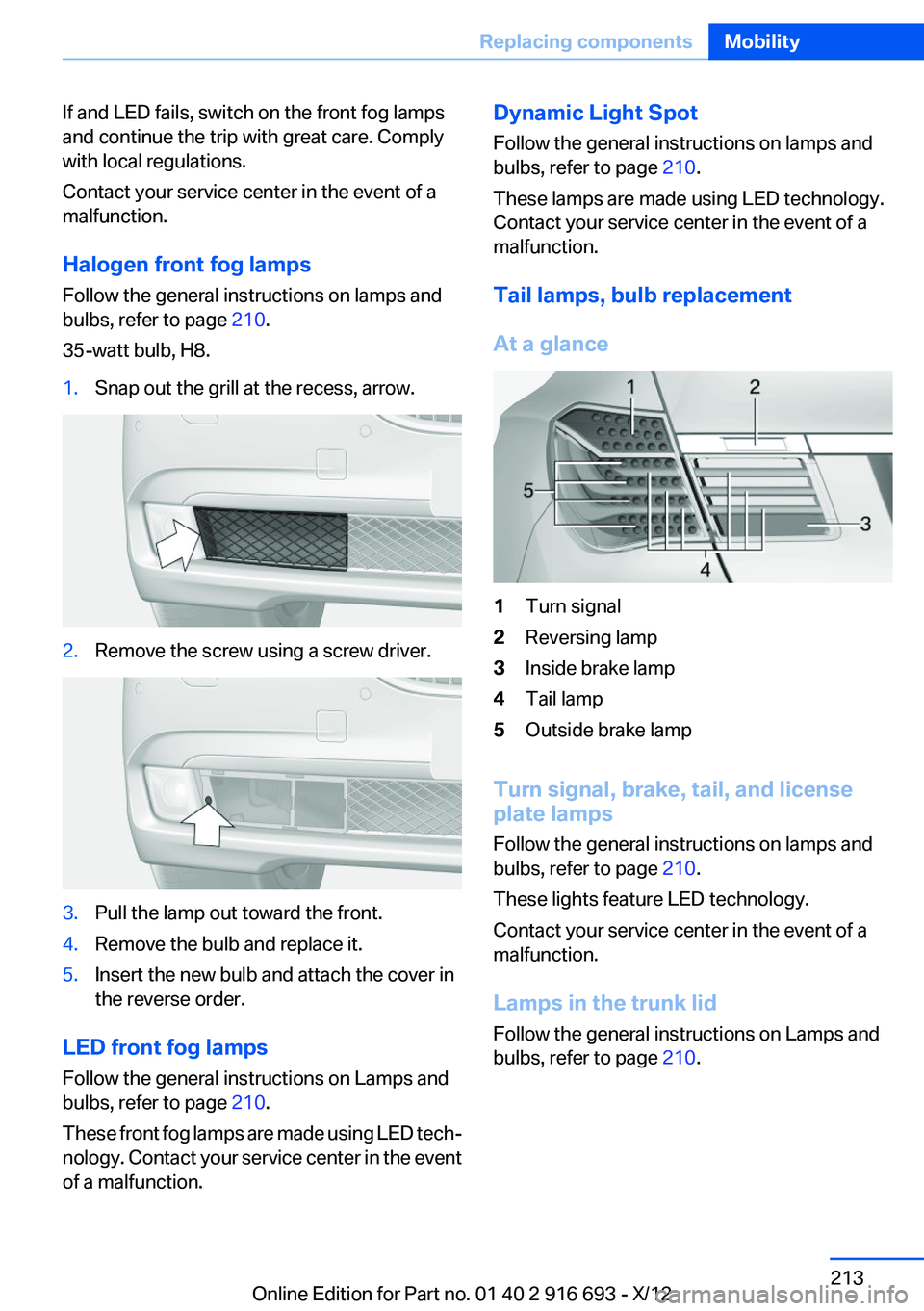
35-watt bulb, H8.1.Snap out the grill at the recess, arrow.2.Remove the screw using a screw driver.3.Pull the lamp out toward the front.4.Remove the bulb and replace it.5.Insert the new bulb and attach the cover in
the reverse order.
LED front fog lamps
Follow the general instructions on Lamps and
bulbs, refer to page 210.
These front fog lamps are made using LED tech‐
nology. Contact your service center in the event
of a malfunction.
Dynamic Light Spot
Follow the general instructions on lamps and
bulbs, refer to page 210.
These lamps are made using LED technology.
Contact your service center in the event of a
malfunction.
Tail lamps, bulb replacement
At a glance1Turn signal2Reversing lamp3Inside brake lamp4Tail lamp5Outside brake lamp
Turn signal, brake, tail, and license
plate lamps
Follow the general instructions on lamps and
bulbs, refer to page 210.
These lights feature LED technology.
Contact your service center in the event of a
malfunction.
Lamps in the trunk lid
Follow the general instructions on Lamps and
bulbs, refer to page 210.
Seite 213Replacing componentsMobility213
Online Edition for Part no. 01 40 2 916 693 - X/12
Page 218 of 243
Assist Response Center contacts you and
takes further steps to help you.
Even if you are unable to respond, the BMW
Assist Response Center can take further
steps to help you under certain circumstan‐
ces.
For this purpose, data that are used to de‐
termine the necessary rescue measures,
such as the current position of the vehicle if
it can be established, are transmitted to the
BMW Assist Response Center.▷If the LED is flashing but the BMW Assist
Response Center cannot be heard on the
hands-free system, the hands-free system
may be malfunctioning. However, the BMW
Assist Response Center may still be able to
hear you.
Initiating an Emergency Request
automatically
Under certain conditions, an Emergency Re‐
quest is automatically initiated immediately after
a severe accident. Automatic Collision Notifica‐
tion is not affected by pressing the SOS button.
Warning triangle
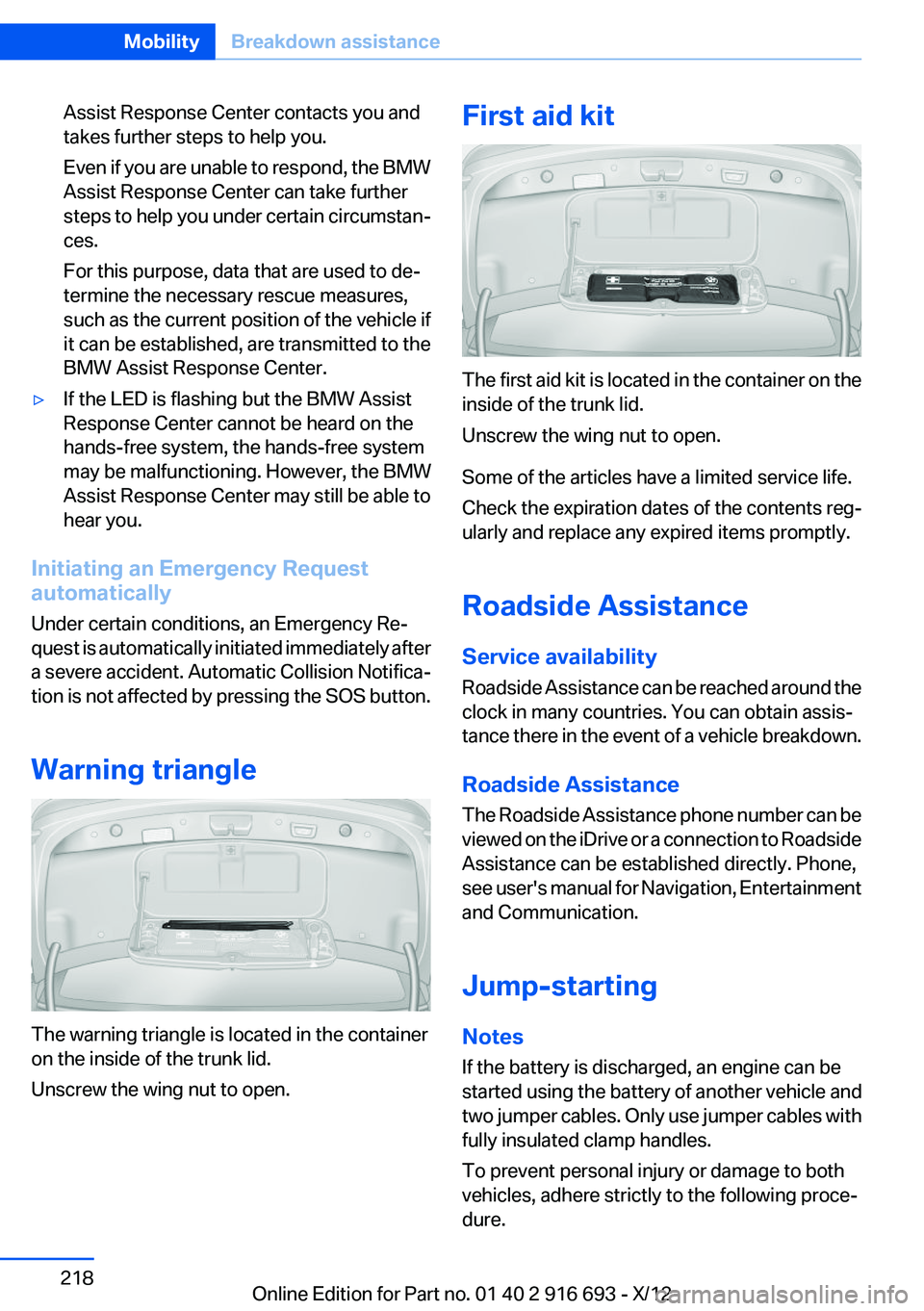
The warning triangle is located in the container
on the inside of the trunk lid.
Unscrew the wing nut to open.
First aid kit
The first aid kit is located in the container on the
inside of the trunk lid.
Unscrew the wing nut to open.
Some of the articles have a limited service life.
Check the expiration dates of the contents reg‐
ularly and replace any expired items promptly.
Roadside Assistance
Service availability
Roadside Assistance can be reached around the
clock in many countries. You can obtain assis‐
tance there in the event of a vehicle breakdown.
Roadside Assistance
The Roadside Assistance phone number can be
viewed on the iDrive or a connection to Roadside
Assistance can be established directly. Phone,
see user's manual for Navigation, Entertainment
and Communication.
Jump-starting
Notes
If the battery is discharged, an engine can be
started using the battery of another vehicle and
two jumper cables. Only use jumper cables with
fully insulated clamp handles.
To prevent personal injury or damage to both
vehicles, adhere strictly to the following proce‐
dure.
Seite 218MobilityBreakdown assistance218
Online Edition for Part no. 01 40 2 916 693 - X/12
Page 221 of 243
Tow fitting
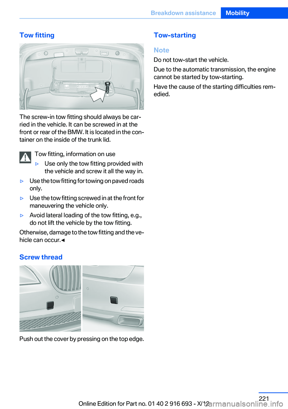
The screw-in tow fitting should always be car‐
ried in the vehicle. It can be screwed in at the
front or rear of the BMW. It is located in the con‐
tainer on the inside of the trunk lid.
Tow fitting, information on use
▷Use only the tow fitting provided with
the vehicle and screw it all the way in.▷Use the tow fitting for towing on paved roads
only.▷Use the tow fitting screwed in at the front for
maneuvering the vehicle only.▷Avoid lateral loading of the tow fitting, e.g.,
do not lift the vehicle by the tow fitting.
Otherwise, damage to the tow fitting and the ve‐
hicle can occur.◀
Screw thread
Push out the cover by pressing on the top edge.
Tow-starting
Note
Do not tow-start the vehicle.
Due to the automatic transmission, the engine
cannot be started by tow-starting.
Have the cause of the starting difficulties rem‐
edied.Seite 221Breakdown assistanceMobility221
Online Edition for Part no. 01 40 2 916 693 - X/12
Page 229 of 243
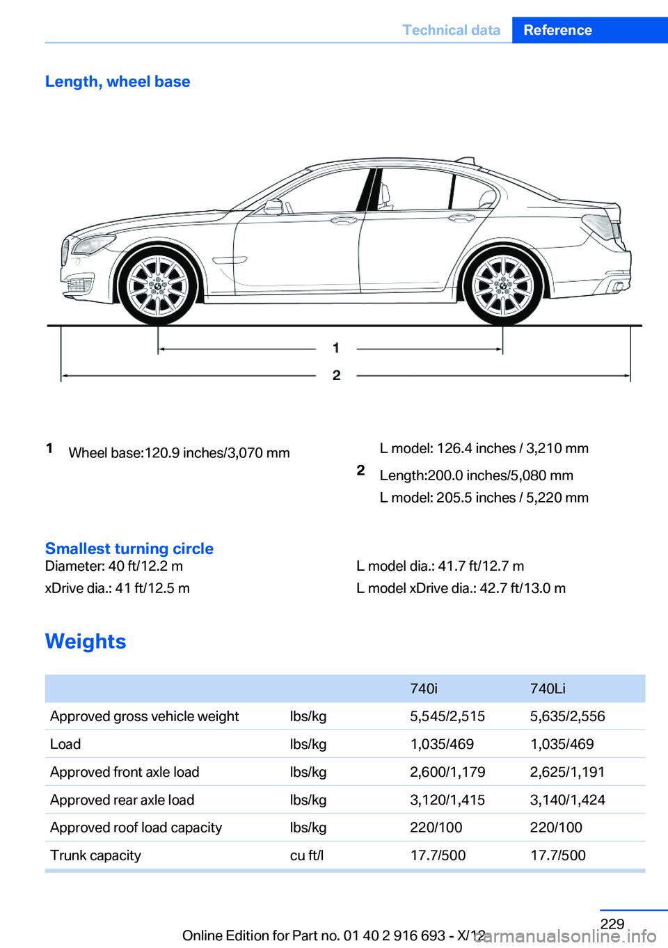
Length, wheel base1Wheel base:120.9 inches/3,070 mmL model: 126.4 inches / 3,210 mm2Length:200.0 inches/5,080 mm
L model: 205.5 inches / 5,220 mm
Smallest turning circle
Diameter: 40 ft/12.2 m
xDrive dia.: 41 ft/12.5 mL model dia.: 41.7 ft/12.7 m
L model xDrive dia.: 42.7 ft/13.0 m
Weights
740i740LiApproved gross vehicle weightlbs/kg5,545/2,5155,635/2,556Loadlbs/kg1,035/4691,035/469Approved front axle loadlbs/kg2,600/1,1792,625/1,191Approved rear axle loadlbs/kg3,120/1,4153,140/1,424Approved roof load capacitylbs/kg220/100220/100Trunk capacitycu ft/l17.7/50017.7/500Seite 229Technical dataReference229
Online Edition for Part no. 01 40 2 916 693 - X/12