2013 BMW 740LI XDRIVE battery
[x] Cancel search: batteryPage 166 of 243
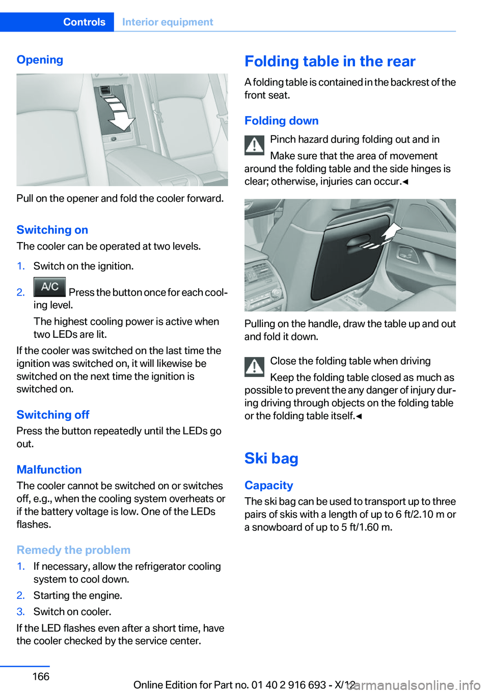
Opening
Pull on the opener and fold the cooler forward.
Switching on
The cooler can be operated at two levels.
1.Switch on the ignition.2. Press the button once for each cool‐
ing level.
The highest cooling power is active when
two LEDs are lit.
If the cooler was switched on the last time the
ignition was switched on, it will likewise be
switched on the next time the ignition is
switched on.
Switching off
Press the button repeatedly until the LEDs go
out.
Malfunction
The cooler cannot be switched on or switches
off, e.g., when the cooling system overheats or
if the battery voltage is low. One of the LEDs
flashes.
Remedy the problem
1.If necessary, allow the refrigerator cooling
system to cool down.2.Starting the engine.3.Switch on cooler.
If the LED flashes even after a short time, have
the cooler checked by the service center.
Folding table in the rear
A folding table is contained in the backrest of the
front seat.
Folding down Pinch hazard during folding out and in
Make sure that the area of movement
around the folding table and the side hinges is
clear; otherwise, injuries can occur.◀
Pulling on the handle, draw the table up and out
and fold it down.
Close the folding table when driving
Keep the folding table closed as much as
possible to prevent the any danger of injury dur‐
ing driving through objects on the folding table
or the folding table itself.◀
Ski bag
Capacity
The ski bag can be used to transport up to three
pairs of skis with a length of up to 6 ft/2.10 m or
a snowboard of up to 5 ft/1.60 m.
Seite 166ControlsInterior equipment166
Online Edition for Part no. 01 40 2 916 693 - X/12
Page 184 of 243
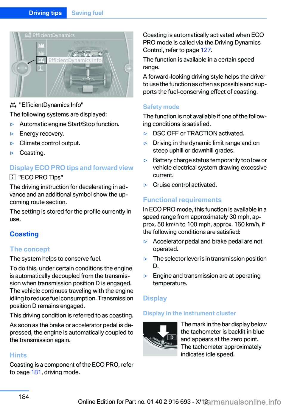
"EfficientDynamics Info"
The following systems are displayed:
▷Automatic engine Start/Stop function.▷Energy recovery.▷Climate control output.▷Coasting.
Display ECO PRO tips and forward view
"ECO PRO Tips"
The driving instruction for decelerating in ad‐
vance and an additional symbol show the up‐
coming route section.
The setting is stored for the profile currently in
use.
Coasting
The concept
The system helps to conserve fuel.
To do this, under certain conditions the engine
is automatically decoupled from the transmis‐
sion when transmission position D is engaged.
The vehicle continues traveling with the engine
idling to reduce fuel consumption. Transmission
position D remains engaged.
This driving condition is referred to as coasting.
As soon as the brake or accelerator pedal is de‐
pressed, the engine is automatically coupled to
the transmission again.
Hints
Coasting is a component of the ECO PRO, refer
to page 181, driving mode.
Coasting is automatically activated when ECO
PRO mode is called via the Driving Dynamics
Control, refer to page 127.
The function is available in a certain speed
range.
A forward-looking driving style helps the driver
to use the function as often as possible and sup‐
ports the fuel-conserving effect of coasting.
Safety mode
The function is not available if one of the follow‐
ing conditions is satisfied.▷DSC OFF or TRACTION activated.▷Driving in the dynamic limit range and on
steep uphill or downhill grades.▷Battery charge status temporarily too low or
vehicle electrical system drawing excessive
current.▷Cruise control activated.
Functional requirements
In ECO PRO mode, this function is available in a
speed range from approximately 30 mph, ap‐
prox. 50 km/h to 100 mph, approx. 160 km/h, if
the following conditions are satisfied:
▷Accelerator pedal and brake pedal are not
operated.▷The selector lever is in transmission position
D.▷Engine and transmission are at operating
temperature.
Display
Display in the instrument cluster The mark in the bar display below
the tachometer is backlit in blue
and appears at the zero point.
The tachometer approximately
indicates idle speed.
Seite 184Driving tipsSaving fuel184
Online Edition for Part no. 01 40 2 916 693 - X/12
Page 215 of 243
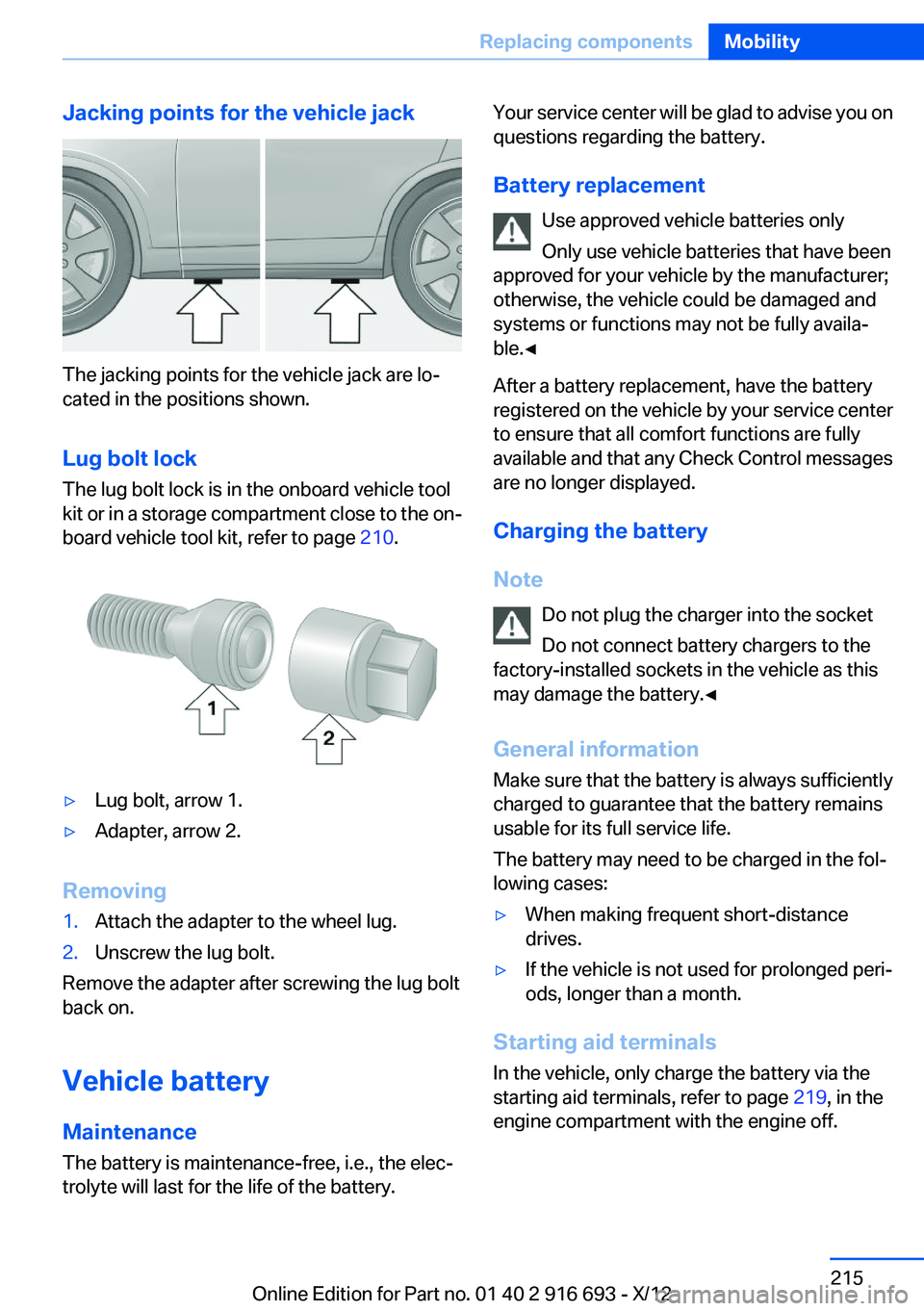
Jacking points for the vehicle jack
The jacking points for the vehicle jack are lo‐
cated in the positions shown.
Lug bolt lock
The lug bolt lock is in the onboard vehicle tool
kit or in a storage compartment close to the on‐
board vehicle tool kit, refer to page 210.
▷Lug bolt, arrow 1.▷Adapter, arrow 2.
Removing
1.Attach the adapter to the wheel lug.2.Unscrew the lug bolt.
Remove the adapter after screwing the lug bolt
back on.
Vehicle battery
Maintenance
The battery is maintenance-free, i.e., the elec‐
trolyte will last for the life of the battery.
Your service center will be glad to advise you on
questions regarding the battery.
Battery replacement Use approved vehicle batteries only
Only use vehicle batteries that have been
approved for your vehicle by the manufacturer;
otherwise, the vehicle could be damaged and
systems or functions may not be fully availa‐
ble.◀
After a battery replacement, have the battery
registered on the vehicle by your service center
to ensure that all comfort functions are fully
available and that any Check Control messages
are no longer displayed.
Charging the battery
Note Do not plug the charger into the socket
Do not connect battery chargers to the
factory-installed sockets in the vehicle as this
may damage the battery.◀
General information
Make sure that the battery is always sufficiently
charged to guarantee that the battery remains
usable for its full service life.
The battery may need to be charged in the fol‐
lowing cases:▷When making frequent short-distance
drives.▷If the vehicle is not used for prolonged peri‐
ods, longer than a month.
Starting aid terminals
In the vehicle, only charge the battery via the
starting aid terminals, refer to page 219, in the
engine compartment with the engine off.
Seite 215Replacing componentsMobility215
Online Edition for Part no. 01 40 2 916 693 - X/12
Page 216 of 243
Power failure
After a temporary power loss, some equipment
needs to be reinitialized.
Individual settings need to be reprogrammed:▷Seat, mirror, and steering wheel memory:
store the positions again.▷Time: update.▷Date: update.▷Radio station: save again.▷Navigation system: wait for the operability of
the navigation.
Disposing of old batteries
Have old batteries disposed of by your
service center or bring them to a recy‐
cling center.
Maintain the battery in an upright position for
transport and storage. Secure the battery so
that it does not tip over during transport.
Fuses
Notes Replacing fuses
Never attempt to repair a blown fuse and
do not replace a defective fuse with a substitute
of another color or amperage rating; this could
lead to a circuit overload, ultimately resulting in
a fire in the vehicle.◀
Plastic tweezers and information on the fuse
types and locations are stored in the fuse box in
the cargo area.
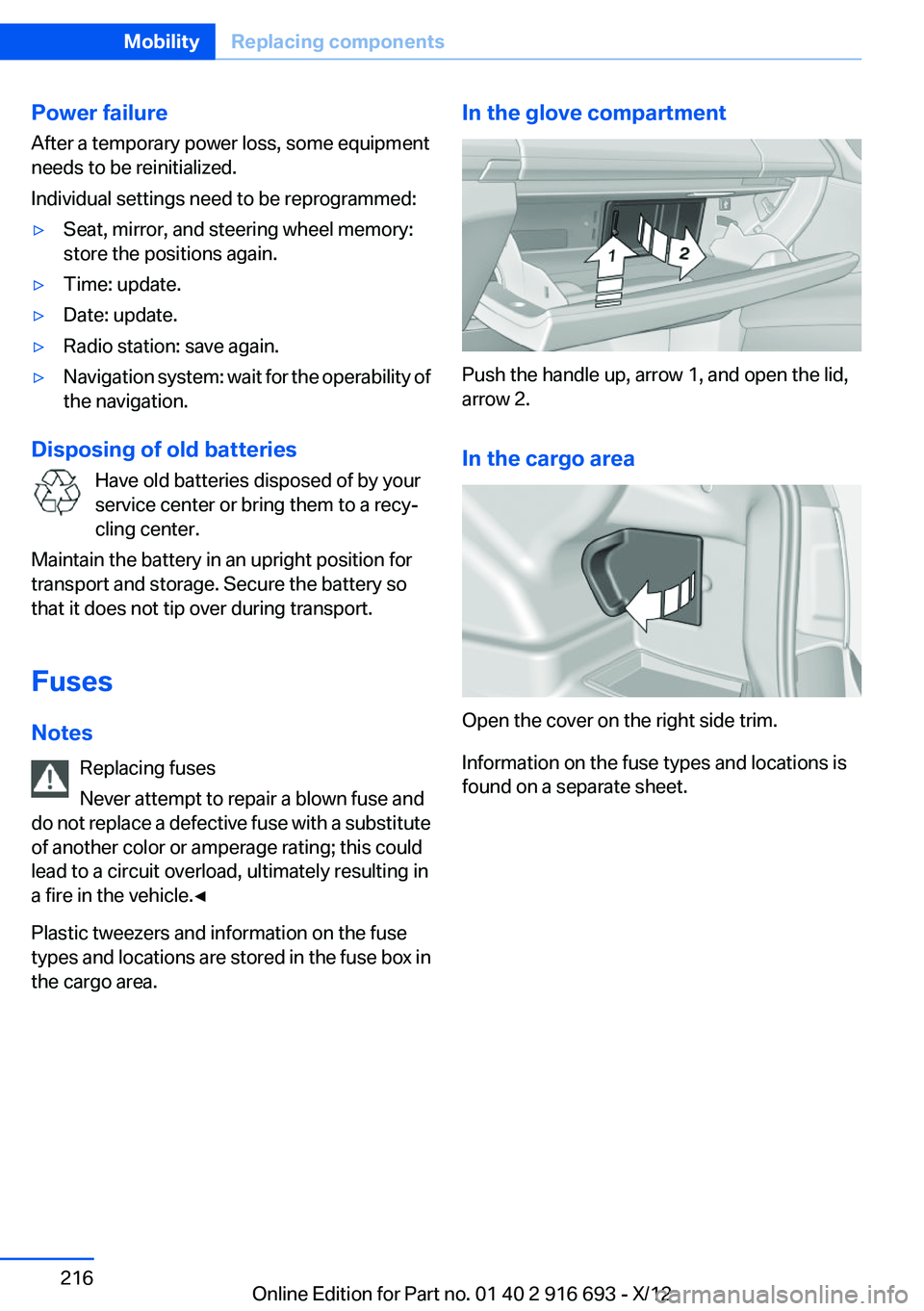
In the glove compartment
Push the handle up, arrow 1, and open the lid,
arrow 2.
In the cargo area
Open the cover on the right side trim.
Information on the fuse types and locations is
found on a separate sheet.
Seite 216MobilityReplacing components216
Online Edition for Part no. 01 40 2 916 693 - X/12
Page 218 of 243
Assist Response Center contacts you and
takes further steps to help you.
Even if you are unable to respond, the BMW
Assist Response Center can take further
steps to help you under certain circumstan‐
ces.
For this purpose, data that are used to de‐
termine the necessary rescue measures,
such as the current position of the vehicle if
it can be established, are transmitted to the
BMW Assist Response Center.▷If the LED is flashing but the BMW Assist
Response Center cannot be heard on the
hands-free system, the hands-free system
may be malfunctioning. However, the BMW
Assist Response Center may still be able to
hear you.
Initiating an Emergency Request
automatically
Under certain conditions, an Emergency Re‐
quest is automatically initiated immediately after
a severe accident. Automatic Collision Notifica‐
tion is not affected by pressing the SOS button.
Warning triangle
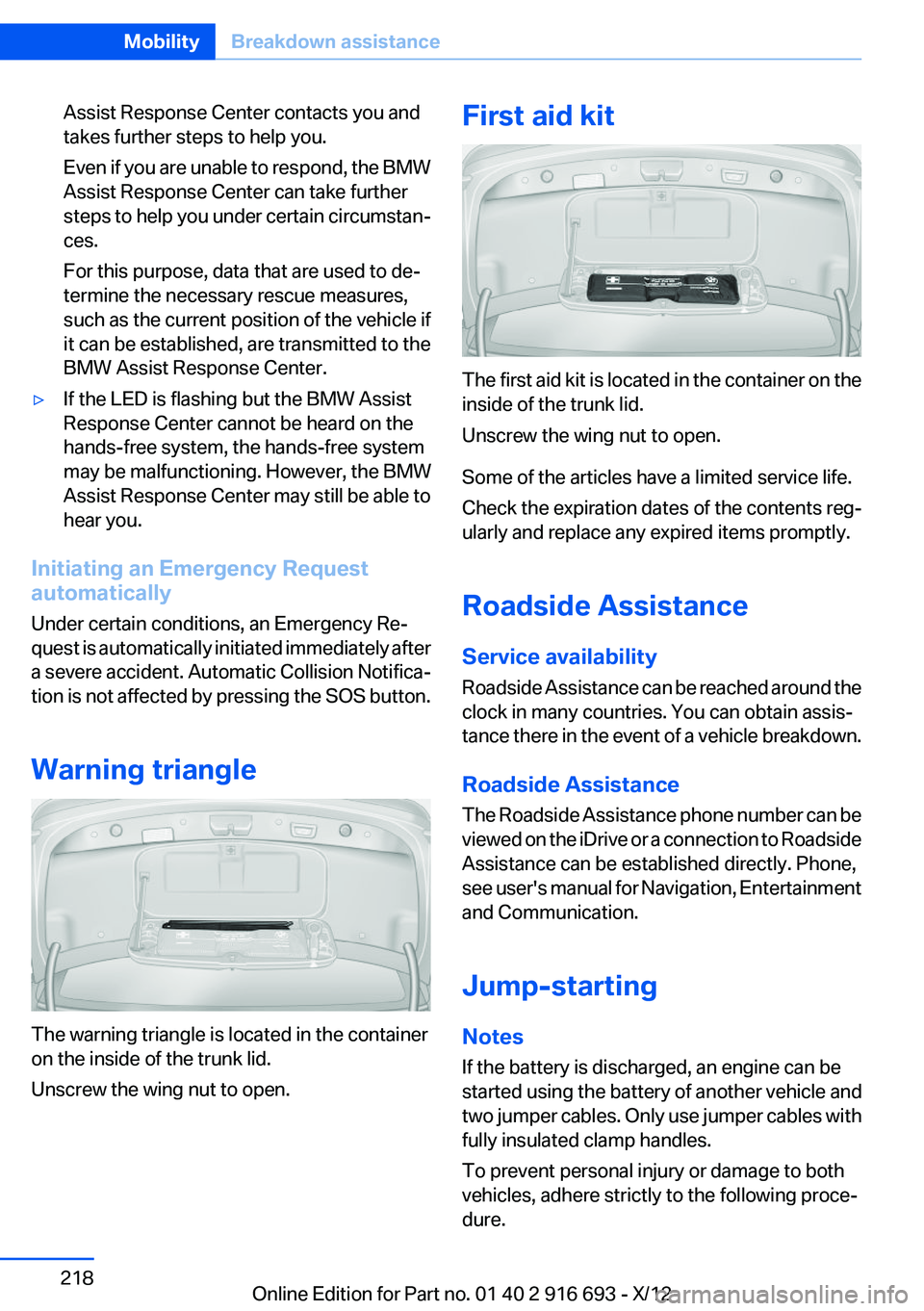
The warning triangle is located in the container
on the inside of the trunk lid.
Unscrew the wing nut to open.
First aid kit
The first aid kit is located in the container on the
inside of the trunk lid.
Unscrew the wing nut to open.
Some of the articles have a limited service life.
Check the expiration dates of the contents reg‐
ularly and replace any expired items promptly.
Roadside Assistance
Service availability
Roadside Assistance can be reached around the
clock in many countries. You can obtain assis‐
tance there in the event of a vehicle breakdown.
Roadside Assistance
The Roadside Assistance phone number can be
viewed on the iDrive or a connection to Roadside
Assistance can be established directly. Phone,
see user's manual for Navigation, Entertainment
and Communication.
Jump-starting
Notes
If the battery is discharged, an engine can be
started using the battery of another vehicle and
two jumper cables. Only use jumper cables with
fully insulated clamp handles.
To prevent personal injury or damage to both
vehicles, adhere strictly to the following proce‐
dure.
Seite 218MobilityBreakdown assistance218
Online Edition for Part no. 01 40 2 916 693 - X/12
Page 219 of 243
Do not touch live parts
To avoid the risk of potentially fatal injury,
always avoid all contact with electrical compo‐
nents while the engine is running.◀
Preparation1.Check whether the battery of the other ve‐
hicle has a voltage of 12 volts. This informa‐
tion can be found on the battery.2.Switch off the engine of the assisting vehi‐
cle.3.Switch off any electronic systems/power
consumers in both vehicles.
Bodywork contact between vehicles
Make sure that there is no contact be‐
tween the bodywork of the two vehicles; other‐
wise, there is the danger of short circuits.◀
Starting aid terminals Connecting order
Connect the jumper cables in the correct
order; otherwise, there is the danger of injury
from sparking.◀
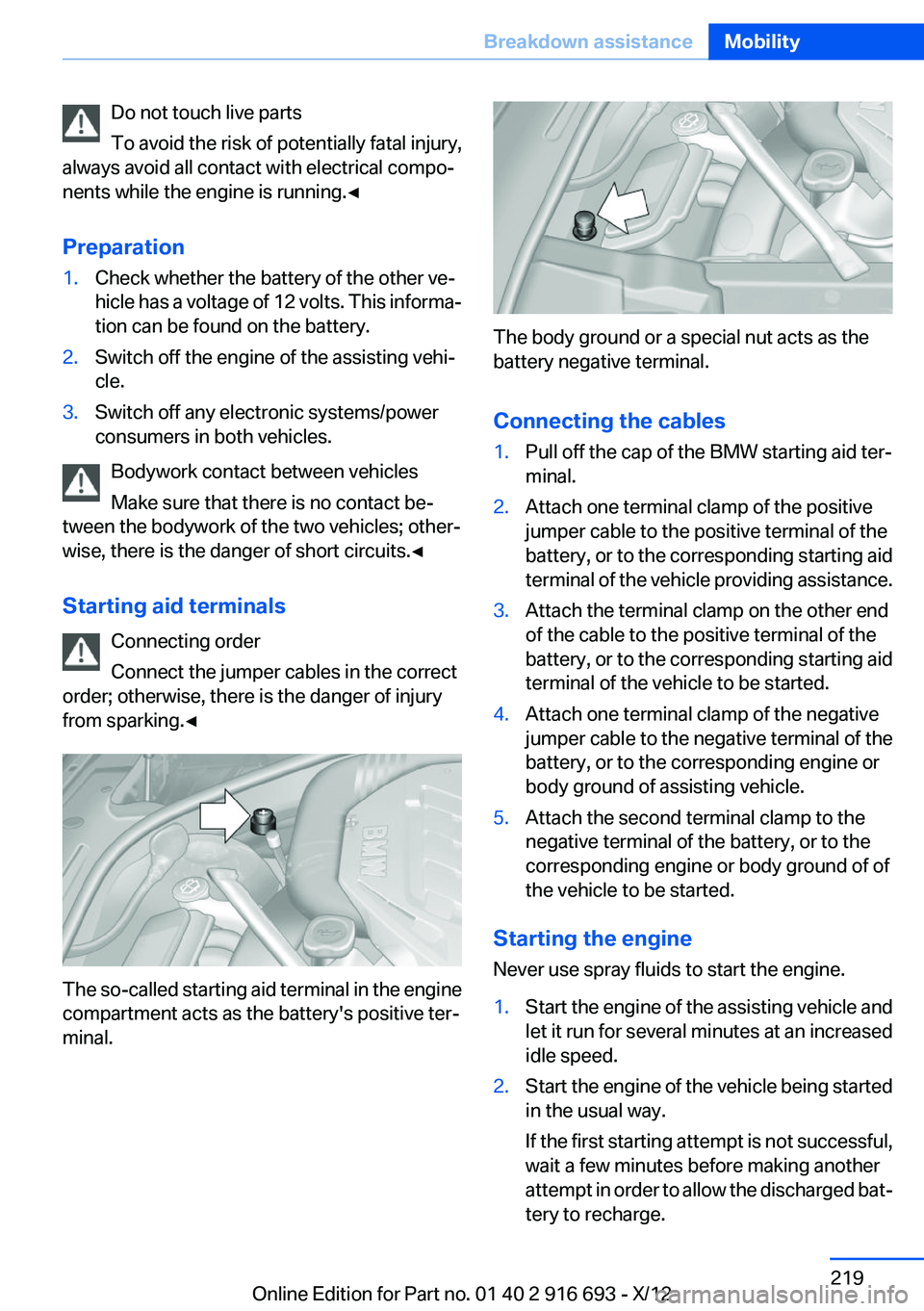
The so-called starting aid terminal in the engine
compartment acts as the battery's positive ter‐
minal.
The body ground or a special nut acts as the
battery negative terminal.
Connecting the cables
1.Pull off the cap of the BMW starting aid ter‐
minal.2.Attach one terminal clamp of the positive
jumper cable to the positive terminal of the
battery, or to the corresponding starting aid
terminal of the vehicle providing assistance.3.Attach the terminal clamp on the other end
of the cable to the positive terminal of the
battery, or to the corresponding starting aid
terminal of the vehicle to be started.4.Attach one terminal clamp of the negative
jumper cable to the negative terminal of the
battery, or to the corresponding engine or
body ground of assisting vehicle.5.Attach the second terminal clamp to the
negative terminal of the battery, or to the
corresponding engine or body ground of of
the vehicle to be started.
Starting the engine
Never use spray fluids to start the engine.
1.Start the engine of the assisting vehicle and
let it run for several minutes at an increased
idle speed.2.Start the engine of the vehicle being started
in the usual way.
If the first starting attempt is not successful,
wait a few minutes before making another
attempt in order to allow the discharged bat‐
tery to recharge.Seite 219Breakdown assistanceMobility219
Online Edition for Part no. 01 40 2 916 693 - X/12
Page 220 of 243

3.Let both engines run for several minutes.4.Disconnect the jumper cables in the reverse
order.
Check the battery and recharge if necessary.
Tow-starting and towing
Transporting your vehicle
Note
Your vehicle is not permitted to be towed.
Therefore, contact a service center in the event
of a breakdown.
Do not have the vehicle towed
Have your vehicle transported on a loading
platform only; otherwise, damage may occur.◀
Tow truck
Do not lift the vehicle
Do not lift the vehicle by the tow fitting or
body and chassis parts; otherwise, damage may
result.◀
Towing other vehicles
General information Light towing vehicle
The towing vehicle must not be lighter
than the vehicle being towed; otherwise, it will
not be possible to control the vehicle re‐
sponse.◀
Attaching the tow bar/tow rope correctly
Attach the tow bar or tow rope to the tow
fitting; connecting it to other vehicle parts may
cause damage.◀▷Switch on the hazard warning system, de‐
pending on local regulations.▷If the electrical system has failed, clearly
identify the vehicle being towed by placing
a sign or a warning triangle in the rear win‐
dow.
Towing methods when towing other
vehicles
Tow bar
The tow fittings used should be on the same
side on both vehicles.
Should it prove impossible to avoid mounting
the tow bar at an offset angle, please observe
the following:
▷Maneuvering capability is limited during cor‐
nering.▷The tow bar will generate lateral forces if it
is secured with an offset.
Tow rope
When starting to tow the vehicle, make sure that
the tow rope is taut.
To avoid jerking and the associated stresses on
the vehicle components when towing, always
use nylon ropes or nylon straps.
Attaching the tow rope correctly
Only secure the tow rope on the tow fit‐
ting; otherwise, damage can occur when it is se‐
cured on other parts of the vehicle.◀
Seite 220MobilityBreakdown assistance220
Online Edition for Part no. 01 40 2 916 693 - X/12
Page 233 of 243
Battery replacement, vehiclebattery 215
Battery replacement, vehicle remote control 30
Battery, vehicle 215
Belts, safety belts 54
Beverage holder, cu‐ pholder 170
Blinds, sun protection 45
BMW Assist, see user's manual for Navigation, Enter‐
tainment and Communica‐
tion
BMW Homepage 6
BMW Internet page 6
BMW maintenance sys‐ tem 208
Bonus range, ECO PRO 182
Bottle holder, refer to Cu‐ pholder 170
Brake assistant 123
Brake discs, breaking in 174
Brake force display 120
Brake lamps, brake force dis‐ play 120
Brake lamps, bulb replace‐ ment 213
Brake lights, adaptive 120
Brake pads, breaking in 174
Braking, notes 175
Breakdown assis‐ tance 217, 218
Breaking in 174
Brightness of Control Dis‐ play 94
Bulb replacement 210
Bulb replacement, rear 213
Bulbs and lamps 210
Button, RES 134
Button, Start/Stop 66
Bypassing, refer to Jump- starting 218 C
California Proposition 65 Warning 7
Camera, backup camera 142
Camera, care 225
Camera, Side View 144
Camera, Top View 145
Can holder, refer to Cu‐ pholder 170
Car battery 215
Car care products 223
Care, displays 225
Care, vehicle 223
Cargo 177
Cargo area lid 37
Cargo area, storage compart‐ ments 170
Cargo straps, securing cargo 178
Car key, refer to Remote con‐ trol 30
Carpet, care 224
Car wash 222
Catalytic converter, refer to Hot exhaust system 174
CBS Condition Based Serv‐ ice 208
CD/Multimedia, see user's manual for Navigation, Enter‐
tainment and Communica‐
tion
Center armrest 169
Center console 14
Central locking system 33
Central screen, refer to Control Display 16
Changes, technical, refer to Safety 7
Changing parts 210
Changing wheels 214
Changing wheels/tires 198
Check Control 83
Children, seating position 62
Children, transporting safely 62 Child restraint fixing sys‐
tem 62
Child restraint fixing system LATCH 63
Child restraint fixing systems, mounting 62
Child safety locks 65
Child seat, mounting 62
Child seats 62
Chrome parts, care 224
Cigarette lighter 163
Cleaning, displays 225
Climate control 154
Climate control on head‐ liner 159
Climate control wind‐ shield 175
Clock 86
Closing/opening from in‐ side 37
Closing/opening via door lock 36
Closing/opening with remote control 34
Clothes hooks 170
Coasting 184
Coasting with engine decou‐ pled, coasting 184
Coasting with idling en‐ gine 184
Collision warning 110
Collision warning with braking function 112
Combination switch, refer to Turn signals 73
Combination switch, refer to Wiper system 74
COMFORT+ program, Driving Dynamics Control 129
Comfort Access 40
COMFORT program, Driving Dynamics Control 129
Computer 90
Condensation on win‐ dows 155 Seite 233Everything from A to ZReference233
Online Edition for Part no. 01 40 2 916 693 - X/12