2013 BMW 740LI mirror
[x] Cancel search: mirrorPage 112 of 243

Collision warning with
braking function
The concept
The system issues a warning if there is imminent
danger of a collision and also includes a braking
function.
If the vehicle is equipped with Active Cruise
Control with Stop & Go, the collision warning is
controlled via the cruise control radar sensor in
conjunction with a camera.
The collision warning is available even if cruise
control has been deactivated.
When the vehicle is intentionally brought into
contact with a vehicle, the collision warning is
delayed to avoid false warnings.
Detection range
Detection range
It responds to stationary or moving objects that
are within the detection range of the radar sys‐
tem.
General information
The system issues a two-phase warning of a
danger of collision at speeds above approx.
10 mph/15 km/h. The time of these warnings
may vary depending on the current driving sit‐
uation.
At a glance
Button in the vehicle
Front protection button.
Radar sensor
Radar sensor
Camera
The camera is located near the base of the mir‐
ror.
Keep the windshield in the area behind the in‐
terior rear view mirror clean and clear.
Seite 112ControlsSafety112
Online Edition for Part no. 01 40 2 916 693 - X/12
Page 117 of 243

▷When the camera is dirty or the protective
glass is damaged.▷In heavy fog, rain or snowfall.▷At very high external temperatures.
Limits of pedestrian detection
Animals are not detected by the pedestrian de‐
tection function, even if they are clearly visible in
the image.
Limited pedestrian detection:
▷People who are fully or partially covered, es‐
pecially when their heads are covered.▷People who are not in an upright position,
e.g., lying down.▷Cyclists on unconventional bicycles (e.g.,
recumbent bicycles).▷After physical damage to the system, e.g.,
after an accident.
No display on the rear screen
The image from Night Vision with people detec‐
tion cannot be displayed on the rear screen.
Lane departure warning
The concept
Starting at a specific speed, this system alerts
you when the vehicle on streets with lane mark‐
ings is about to leave the lane. Depending on the
country-specific version of the vehicle, the
speed is between 35 mph/55 km/h and
45 mph/70 km/h. When switching on the system
below this speed, a message appears in the in‐
strument cluster.
The steering wheel begins vibrating gently in the
event of warnings. The time of the warning may
vary depending on the current driving situation.
The system does not provide a warning if the
turn signal is set before leaving the lane.
Notes
Personal responsibility
The system cannot serve as a substitute
for the driver's personal judgment of the course
of the road and the traffic situation.
In the event of a warning, do not jerk the steering
wheel, as you may lose control of the vehicle.◀
At a glance
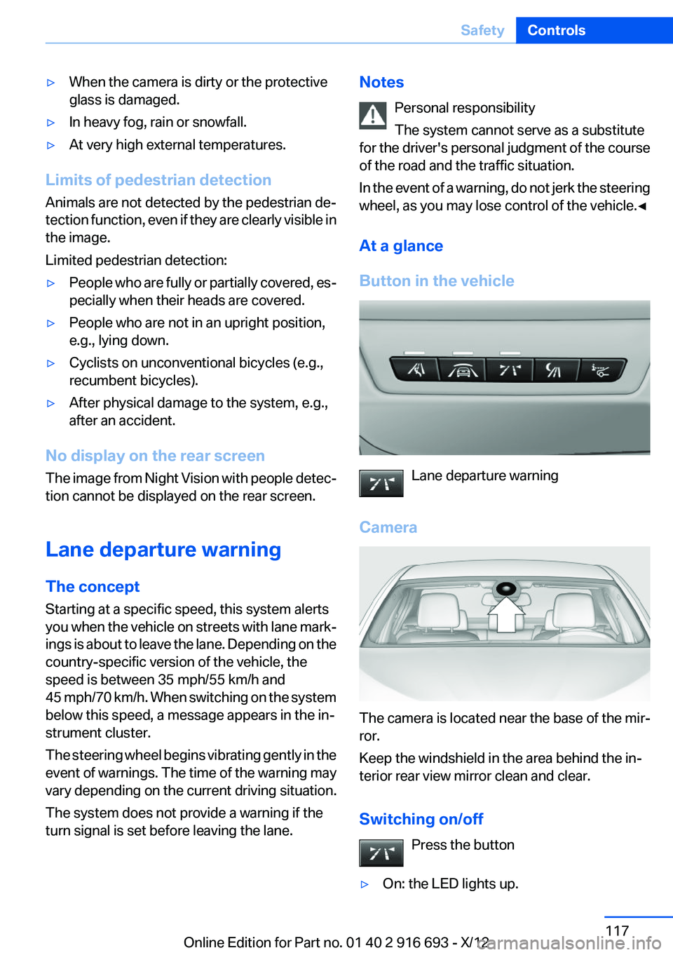
Button in the vehicle
Lane departure warning
Camera
The camera is located near the base of the mir‐
ror.
Keep the windshield in the area behind the in‐
terior rear view mirror clean and clear.
Switching on/off Press the button
▷On: the LED lights up.Seite 117SafetyControls117
Online Edition for Part no. 01 40 2 916 693 - X/12
Page 118 of 243

▷Off: the LED goes out.
The state is stored for the remote control cur‐
rently in use.
Display in the instrument cluster
▷Lines: system is activated.▷Arrows: at least one lane marking
was detected and warnings can be
issued.
Display in the instrument display
▷Symbol red: system is activated.▷Symbol green: at least one lane
marking was detected and warnings
can be issued.
Issued warning
If you leave the lane and if a lane marking has
been detected, the steering wheel begins vi‐
brating.
If the turn signal is set before changing the lane,
a warning is not issued.
End of warning
The warning ends:
▷Automatically after approx. 3 seconds.▷When returning to your own lane.▷When braking hard.▷When using the turn signal.
System limits
The system may not be fully functional in the
following situations:
▷In heavy fog, rain or snowfall.▷In the event of worn, poorly visible, merging,
diverging, or multiple lane markings such as
in construction areas.▷When lane markings are covered in snow,
ice, dirt or water.▷In tight curves or on narrow lanes.▷When the lane markings are covered by ob‐
jects.▷When driving very close to the vehicle in
front of you.▷When driving toward bright lights.▷When the windshield behind the interior
rearview mirror is fogged over, dirty or cov‐
ered with stickers, etc.▷During calibration of the camera immedi‐
ately after vehicle shipment.
Active Blind Spot Detection
The concept
Two radar sensors below the rear bumper mon‐
itor the area behind and next to the vehicle at
speeds above approx. 30 mph/50 km/h.
The system indicates whether there are vehicles
in the blind spot, arrow 1, or approaching from
behind on the adjacent lane, arrow 2.
The lamp in the exterior mirror housing lights up
dimly.
Before you change lanes after setting the turn
signal, the system issues a warning in the situa‐
tions described above.
The lamp in the housing of the exterior mirror
flashes and the steering wheel vibrates.
Seite 118ControlsSafety118
Online Edition for Part no. 01 40 2 916 693 - X/12
Page 119 of 243

NotesPersonal responsibility
The system does not serve as a substitute
for the driver's personal judgment of the traffic
situation.
Be aware of the traffic situation and the vehicle's
surroundings at all times, otherwise an accident
is still possible despite all warnings.◀
At a glance
Radar sensors
The radar sensors are located under the rear
bumper.
Switching on/off
Press the button.
▷On: the LED lights up.▷Off: the LED goes out.
The system can issue warnings at speeds above
approx. 30 mph/50 km/h.
The state is stored for the remote control cur‐
rently in use.
Display
Information stage
The dimmed lamp in the mirror housing indi‐
cates when there are vehicles in the blind spot
or approaching from behind.
Warning
If the turn signal is set while a vehicle is in the
critical zone, the steering wheel vibrates briefly
and the lamp in the mirror housing flashes
brightly.
The warning stops when the turn signal is
switched off, or the other vehicle leaves the crit‐
ical zone.
System limits
The system may not be fully functional in the
following situations:
▷When a vehicle is approaching at a speed
much faster than your own.▷In heavy fog, rain or snowfall.▷In tight curves or on narrow lanes.▷If the bumper is dirty or iced up, or covered
with stickers.
A Check Control message is displayed when the
system is not fully functional.
For US owners only
The transmitter and receiver units comply with
part 15 of the FCC/Federal Communication
Commission regulations. Operation is governed
by the following:
FCC ID:
Seite 119SafetyControls119
Online Edition for Part no. 01 40 2 916 693 - X/12
Page 132 of 243

Radar sensor
A dirty or covered sensor may hinder the detec‐
tion of vehicles.
▷If necessary, clean the radar sensor. Re‐
move layers of snow and ice carefully.▷Do not cover the view field of the radar sen‐
sor.
Camera
The camera is located near the base of the mir‐
ror.
Keep the windshield in the area behind the in‐
terior rear view mirror clean and clear.
Switching on/off and interrupting
cruise control
Switching on Press the button on the steering wheel.
The indicator lamps in the instrument cluster
light up and the mark in the speedometer is set
to the current speed.
Cruise control can be used.
Switching off
Deactivated or interrupted system
If the system is deactivated or interrupted,
actively intervene by braking and, if necessary,
with evasive maneuvers; otherwise, there is the
danger of an accident occurring.◀
If switching off the system while stationary,
press on the brake pedal at the same time.
Press the button on the steering wheel.▷If active: press twice.▷If interrupted: press once.
The displays go out. The stored desired speed
and distance are deleted.
Interrupting the system Press the button on the steering wheel.
If interrupting the system while stationary, press
on the brake pedal at the same time.
The system is automatically interrupted in the
following situations:
▷When the brakes are applied.▷When transmission position D is disen‐
gaged.▷When DTC Dynamic Traction Control is ac‐
tivated or DSC is deactivated.▷When DSC is actively controlling stability.▷If the safety belt and the driver's door are
opened when the vehicle is standing still.▷If the system has not detected objects for an
extended period, e.g., on a road with very lit‐
tle traffic without road edge line markings.▷If the radar sensor is dirty.
Maintaining/storing the speed
Press the button.
Or:
Seite 132ControlsDriving comfort132
Online Edition for Part no. 01 40 2 916 693 - X/12
Page 145 of 243

Switch the system back on if necessary.
Display
The traffic area to the left and right is displayed
on the Control Display.
Guidelines at the bottom of the image show the
position of the front of the vehicle.
Brightness
With the Side View switched on:
1. "Brightness"2.Turn the controller until the desired setting
is reached and press the controller.
Contrast
With the Side View switched on:
1. "Contrast"2.Turn the controller until the desired setting
is reached and press the controller.
System limits
The cameras capture a maximum range of
330 ft/100 m.
Top View
The concept
Top View assists you in parking and maneuver‐
ing. The area around the doors and the road area
around the vehicle are shown on the Control
Display for this purpose.
General information
The image is captured by two cameras
integrated in the exterior mirrors and by the
backup camera.
The range is at least 7 ft/2 m to the side and rear.
In this way, obstacles up to the height of the ex‐
terior mirrors are detected early.
Notes Check the traffic situation as well
Check the traffic situation around the ve‐
hicle with your own eyes. Otherwise, an accident
could result from road users or objects located
outside the picture area of the cameras.◀
At a glance
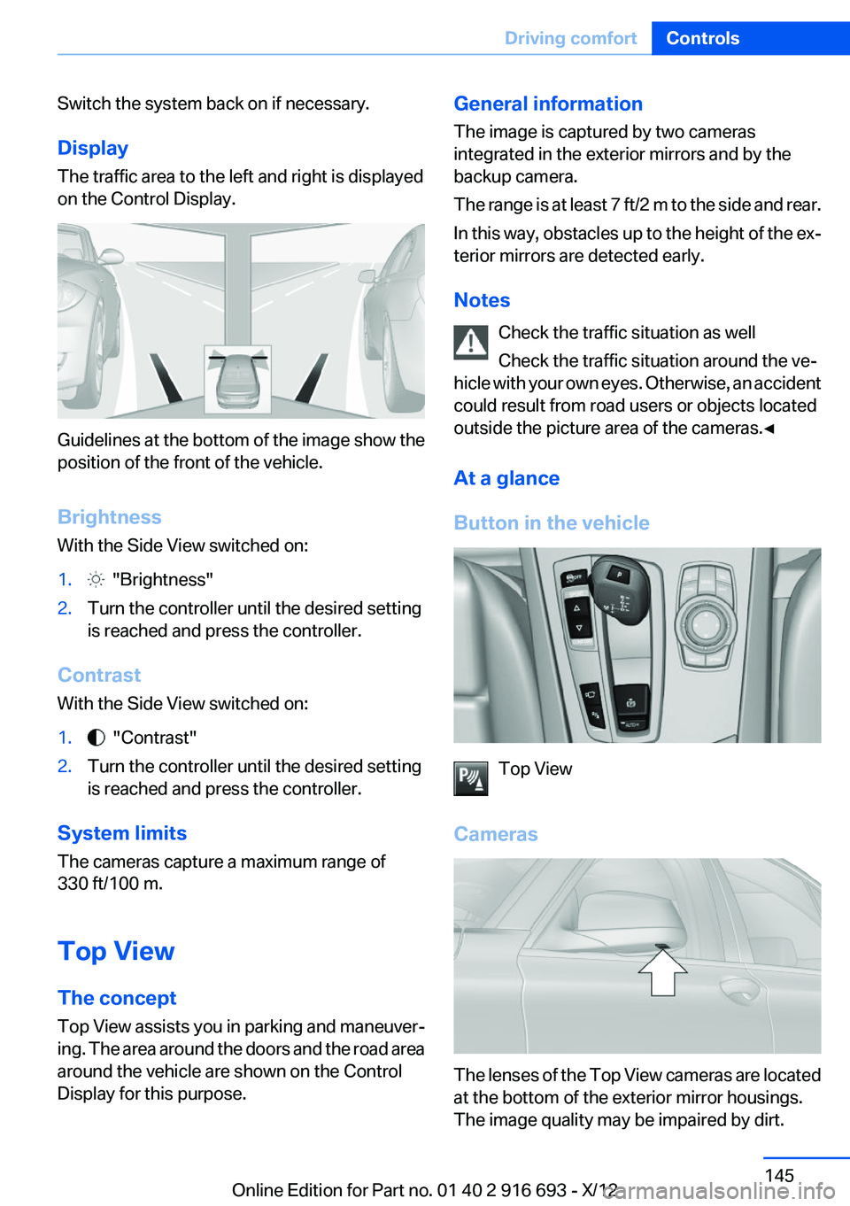
Button in the vehicle
Top View
Cameras
The lenses of the Top View cameras are located
at the bottom of the exterior mirror housings.
The image quality may be impaired by dirt.
Seite 145Driving comfortControls145
Online Edition for Part no. 01 40 2 916 693 - X/12
Page 147 of 243

The pathway line is dependent on the cur‐
rent steering angle and is continuously ad‐
justed with the steering wheel movement.
"Parking aid lines"
Turning circle and pathway lines are displayed.
System limits
Top View cannot be used in the following situa‐
tions:
▷With a door open.▷With the trunk lid open.▷With an exterior mirror folded in.▷In poor light.
A Check Control message is displayed in some
of these situations.
Parking assistant
The concept
This system assists the driver in parking parallel
to the road.
Ultrasound sensors measure parking spaces on
both sides of the vehicle.
The parking assistant calculates the best pos‐
sible parking line and takes control of steering
during the parking procedure.
A component of the parking assistant is the PDC
Park Distance Control, refer to page 139.
Notes
Personal responsibility
The parking assistant does not relieve the
driver of responsibility for the vehicle during the
parking procedure.
Watch the parking space and parking procedure
closely and intervene if necessary; otherwise,
there is the danger of an accident.◀
Changes to the parking space
Changes to the parking space after it was
measured are not taken into account by the sys‐
tem.
Therefore, always be alert and ready to inter‐
vene; otherwise, there is the danger of an acci‐
dent occurring.◀
Transporting loads
Loads that extend beyond the perimeter
of the vehicle are not taken into account by the
system during the parking procedure.
Therefore, always be alert and ready to inter‐
vene; otherwise, there is the danger of an acci‐
dent occurring.◀
Curbs
The parking assistant may steer the vehi‐
cle over or onto curbs.
Therefore, always be alert and ready to inter‐
vene; otherwise, the wheels, tires, or the vehicle
may become damaged.◀
An engine that has been switched off by the
Auto Start Stop function is restarted automati‐
cally when the parking assistant is activated.
Requirements
For measuring parking spaces▷Maximum speed while driving forward ap‐
prox. 22 mph/35 km/h.▷Maximum distance to row of parked vehi‐
cles: 5 ft/1.5 m.Seite 147Driving comfortControls147
Online Edition for Part no. 01 40 2 916 693 - X/12
Page 161 of 243

Interior equipmentVehicle equipment
All standard, country-specific and optional
equipment that is offered in the model series is
described in this chapter. Therefore, equipment
is also described that is not available in a vehicle,
e. g., because of the selected optional equip‐
ment or country variant. This also applies for
safety-related functions and systems.
Integrated universal remote
control
The concept
The integrated universal remote control can op‐
erate up to 3 functions of remote-controlled sys‐
tems such as garage door drives or lighting sys‐
tems. The integrated universal remote control
replaces up to 3 different hand-held transmit‐
ters. To operate the remote control, the buttons
on the interior rearview mirror must be program‐
med with the desired functions. The hand-held
transmitter for the particular system is required
in order to program the remote control.
During programming
During programming and before activat‐
ing a device using the integrated universal re‐
mote control, ensure that there are no people,
animals, or objects in the range of movement of
the remote-controlled device; otherwise, there
is a risk of injury or damage.
Also follow the safety instructions of the hand-
held transmitter.◀
Before selling the vehicle, delete the stored
functions for the sake of security.
Compatibility If this symbol is printed on the packaging
or in the instructions of the system to be
controlled, the system is generally com‐patible with the integrated universal remote
control.
If you have any questions, please contact:▷Your service center.▷www.homelink.com on the Internet.
HomeLink is a registered trademark of Johnson
Controls, Inc.
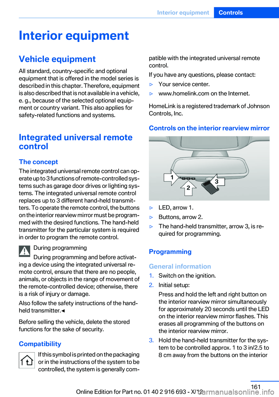
Controls on the interior rearview mirror
▷LED, arrow 1.▷Buttons, arrow 2.▷The hand-held transmitter, arrow 3, is re‐
quired for programming.
Programming
General information
1.Switch on the ignition.2.Initial setup:
Press and hold the left and right button on
the interior rearview mirror simultaneously
for approximately 20 seconds until the LED
on the interior rearview mirror flashes. This
erases all programming of the buttons on
the interior rearview mirror.3.Hold the hand-held transmitter for the sys‐
tem to be controlled approx. 1 to 3 in/2.5 to
8 cm away from the buttons on the interiorSeite 161Interior equipmentControls161
Online Edition for Part no. 01 40 2 916 693 - X/12