2013 BMW 740LI ECU
[x] Cancel search: ECUPage 117 of 243
▷When the camera is dirty or the protective
glass is damaged.▷In heavy fog, rain or snowfall.▷At very high external temperatures.
Limits of pedestrian detection
Animals are not detected by the pedestrian de‐
tection function, even if they are clearly visible in
the image.
Limited pedestrian detection:
▷People who are fully or partially covered, es‐
pecially when their heads are covered.▷People who are not in an upright position,
e.g., lying down.▷Cyclists on unconventional bicycles (e.g.,
recumbent bicycles).▷After physical damage to the system, e.g.,
after an accident.
No display on the rear screen
The image from Night Vision with people detec‐
tion cannot be displayed on the rear screen.
Lane departure warning
The concept
Starting at a specific speed, this system alerts
you when the vehicle on streets with lane mark‐
ings is about to leave the lane. Depending on the
country-specific version of the vehicle, the
speed is between 35 mph/55 km/h and
45 mph/70 km/h. When switching on the system
below this speed, a message appears in the in‐
strument cluster.
The steering wheel begins vibrating gently in the
event of warnings. The time of the warning may
vary depending on the current driving situation.
The system does not provide a warning if the
turn signal is set before leaving the lane.
Notes
Personal responsibility
The system cannot serve as a substitute
for the driver's personal judgment of the course
of the road and the traffic situation.
In the event of a warning, do not jerk the steering
wheel, as you may lose control of the vehicle.◀
At a glance
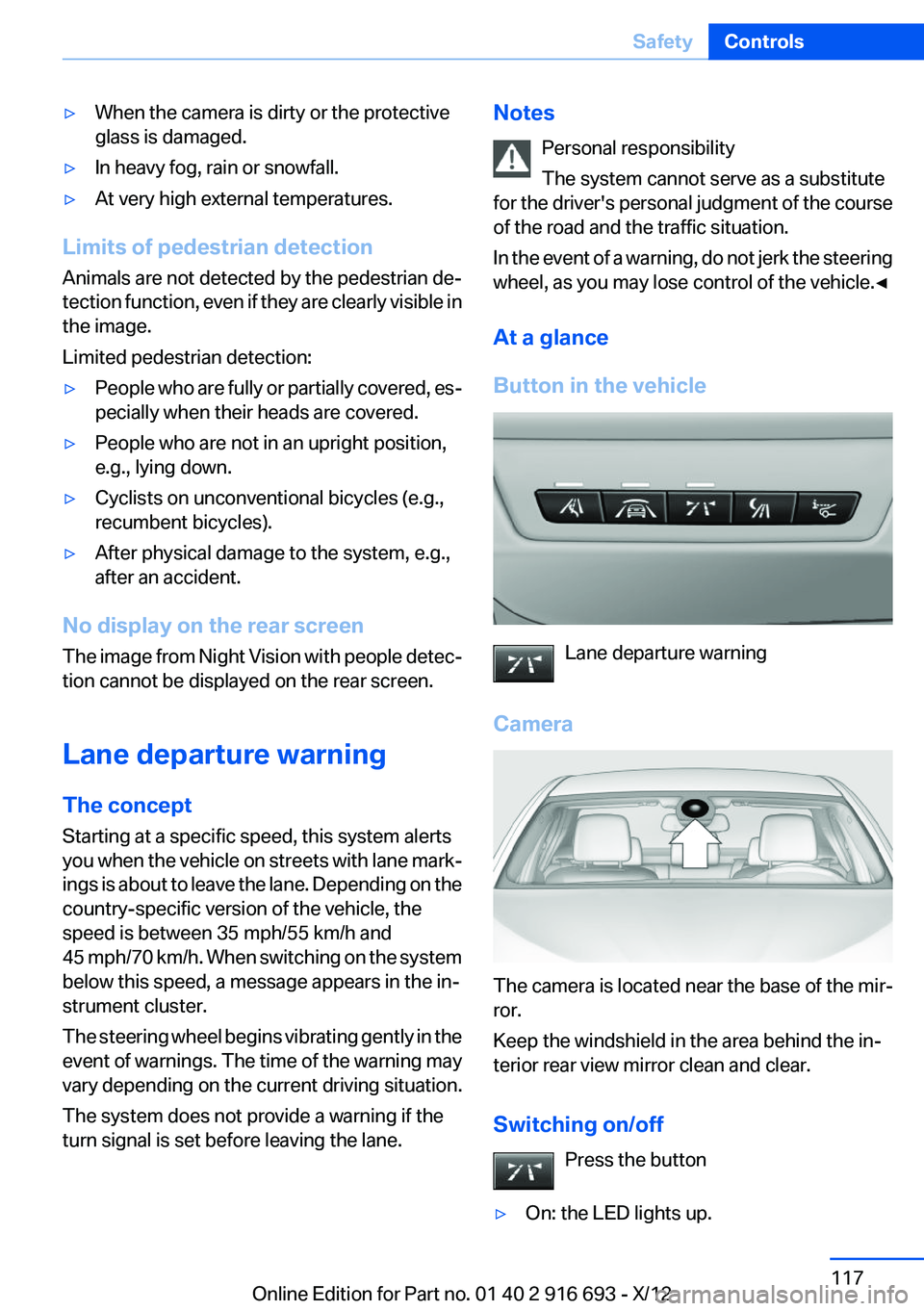
Button in the vehicle
Lane departure warning
Camera
The camera is located near the base of the mir‐
ror.
Keep the windshield in the area behind the in‐
terior rear view mirror clean and clear.
Switching on/off Press the button
▷On: the LED lights up.Seite 117SafetyControls117
Online Edition for Part no. 01 40 2 916 693 - X/12
Page 122 of 243
standstill. This can reduce the risk of a further
collision and the consequences thereof.
Depressing the brake pedal can cause the vehi‐
cle to brake harder. This interrupts automatic
braking. Depressing the accelerator pedal also
interrupts automatic braking.
After coming to a halt, the brake is released au‐
tomatically. Secure the vehicle against rolling.Seite 122ControlsSafety122
Online Edition for Part no. 01 40 2 916 693 - X/12
Page 134 of 243

The selected distance, refer to page 134, is dis‐
played in the instrument cluster.
Calling up the desired speed and
distance
While driving Press the button with the system
switched on.
In the following cases, the stored speed value is
deleted and cannot be called up again:▷When the system is switched off.▷When the ignition is switched off.
While standing
Before leaving the vehicle, secure it
against rolling.
Before leaving the vehicle with the engine run‐
ning, engage position P of the automatic trans‐
mission and apply the parking brake. Otherwise,
the vehicle may begin to roll.◀
The system brought the vehicle to a complete
standstill.
▷Green mark in the speedometer during a
brief idle phase:
The vehicle ahead of you drives away while
the mark is green: your vehicle accelerates
without anything having to be done.▷Switch to orange of the mark in the speed‐
ometer after approx. 2 sec.:
The vehicle ahead of you drives away, while
the mark is orange: in order to accelerate,
briefly press the gas pedal or press the RES
button or SET button.
Rolling bars in the distance indicator mean that
the vehicle ahead of you has driven off.
You actively braked your vehicle to a halt by
pressing on the brake pedal and it is standing
behind another vehicle:1. Press the button to call up a stored
desired speed.2.Release the brake pedal.3.Press on the accelerator briefly, or press the
RES button or the rocker switch when the
vehicle ahead of you drives away.
Displays in the instrument cluster
Desired speed
▷The marking lights up green:
the system is active.▷The marking lights up or‐
ange: the system has been
interrupted.▷The marking does not light up: the system is
switched off.
With instrument display: the symbol is
displayed in the speedometer similarly
to the mark for the desired speed.
Brief status display Selected desired speed.
If --- appears briefly on the display for Check
Control messages, it is possible that the system
requirements for operation are currently not
met.
Distance to vehicle ahead of you
The selected distance to the vehicle driving
ahead of you is shown.
Seite 134ControlsDriving comfort134
Online Edition for Part no. 01 40 2 916 693 - X/12
Page 161 of 243
Interior equipmentVehicle equipment
All standard, country-specific and optional
equipment that is offered in the model series is
described in this chapter. Therefore, equipment
is also described that is not available in a vehicle,
e. g., because of the selected optional equip‐
ment or country variant. This also applies for
safety-related functions and systems.
Integrated universal remote
control
The concept
The integrated universal remote control can op‐
erate up to 3 functions of remote-controlled sys‐
tems such as garage door drives or lighting sys‐
tems. The integrated universal remote control
replaces up to 3 different hand-held transmit‐
ters. To operate the remote control, the buttons
on the interior rearview mirror must be program‐
med with the desired functions. The hand-held
transmitter for the particular system is required
in order to program the remote control.
During programming
During programming and before activat‐
ing a device using the integrated universal re‐
mote control, ensure that there are no people,
animals, or objects in the range of movement of
the remote-controlled device; otherwise, there
is a risk of injury or damage.
Also follow the safety instructions of the hand-
held transmitter.◀
Before selling the vehicle, delete the stored
functions for the sake of security.
Compatibility If this symbol is printed on the packaging
or in the instructions of the system to be
controlled, the system is generally com‐patible with the integrated universal remote
control.
If you have any questions, please contact:▷Your service center.▷www.homelink.com on the Internet.
HomeLink is a registered trademark of Johnson
Controls, Inc.
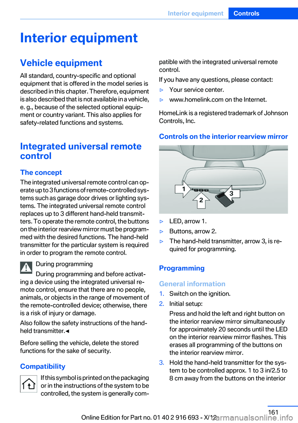
Controls on the interior rearview mirror
▷LED, arrow 1.▷Buttons, arrow 2.▷The hand-held transmitter, arrow 3, is re‐
quired for programming.
Programming
General information
1.Switch on the ignition.2.Initial setup:
Press and hold the left and right button on
the interior rearview mirror simultaneously
for approximately 20 seconds until the LED
on the interior rearview mirror flashes. This
erases all programming of the buttons on
the interior rearview mirror.3.Hold the hand-held transmitter for the sys‐
tem to be controlled approx. 1 to 3 in/2.5 to
8 cm away from the buttons on the interiorSeite 161Interior equipmentControls161
Online Edition for Part no. 01 40 2 916 693 - X/12
Page 167 of 243
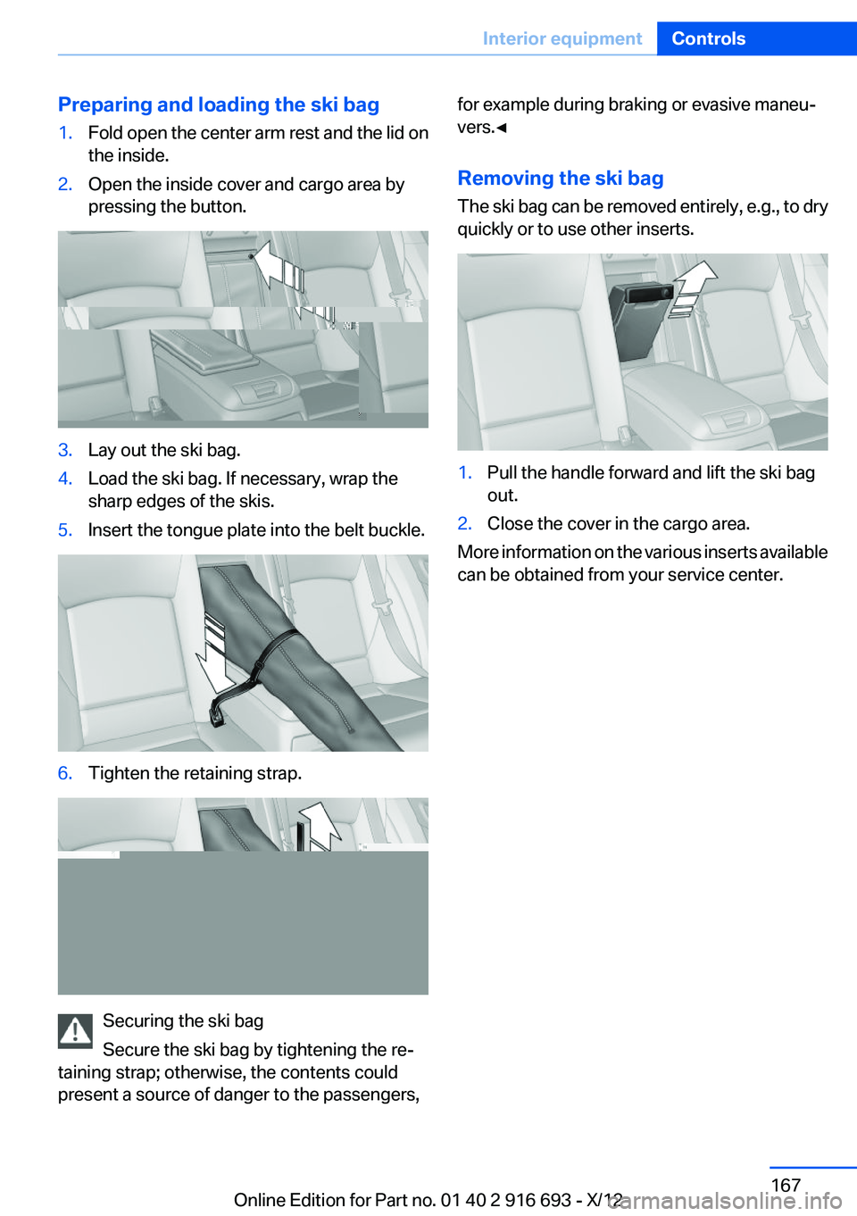
Preparing and loading the ski bag1.Fold open the center arm rest and the lid on
the inside.2.Open the inside cover and cargo area by
pressing the button.3.Lay out the ski bag.4.Load the ski bag. If necessary, wrap the
sharp edges of the skis.5.Insert the tongue plate into the belt buckle.6.Tighten the retaining strap.
Securing the ski bag
Secure the ski bag by tightening the re‐
taining strap; otherwise, the contents could
present a source of danger to the passengers,
for example during braking or evasive maneu‐
vers.◀
Removing the ski bag
The ski bag can be removed entirely, e.g., to dry
quickly or to use other inserts.1.Pull the handle forward and lift the ski bag
out.2.Close the cover in the cargo area.
More information on the various inserts available
can be obtained from your service center.
Seite 167Interior equipmentControls167
Online Edition for Part no. 01 40 2 916 693 - X/12
Page 168 of 243
Storage compartmentsVehicle equipment
All standard, country-specific and optional
equipment that is offered in the model series is
described in this chapter. Therefore, equipment
is also described that is not available in a vehicle,
e. g., because of the selected optional equip‐
ment or country variant. This also applies for
safety-related functions and systems.
Notes No loose objects in the passenger com‐
partment
Do not stow any objects in the passenger com‐
partment without securing them; otherwise,
they may present a danger to occupants for in‐
stance during braking and avoidance maneu‐
vers.◀
Do not place anti-slip mats on the dash‐
board
Do not place anti-slip mats on the dashboard.
The mat materials could damage the dash‐
board.◀
Storage compartments
The following storage compartments are avail‐
able in the vehicle interior:▷Glove compartment on the driver's and front
passenger side, refer to page 168.▷Storage compartment in the center armrest,
refer to page 169, in the front and rear.▷Compartments in the doors.▷Pockets on the backrests of the front seats.▷Net in the front passenger footwell.Glove compartment
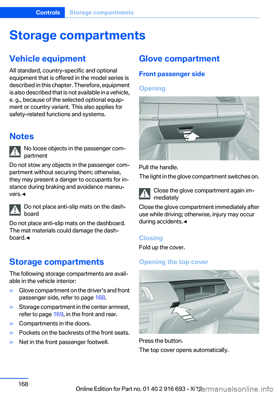
Front passenger side
Opening
Pull the handle.
The light in the glove compartment switches on.
Close the glove compartment again im‐
mediately
Close the glove compartment immediately after
use while driving; otherwise, injury may occur
during accidents.◀
Closing
Fold up the cover.
Opening the top cover
Press the button.
The top cover opens automatically.
Seite 168ControlsStorage compartments168
Online Edition for Part no. 01 40 2 916 693 - X/12
Page 171 of 243
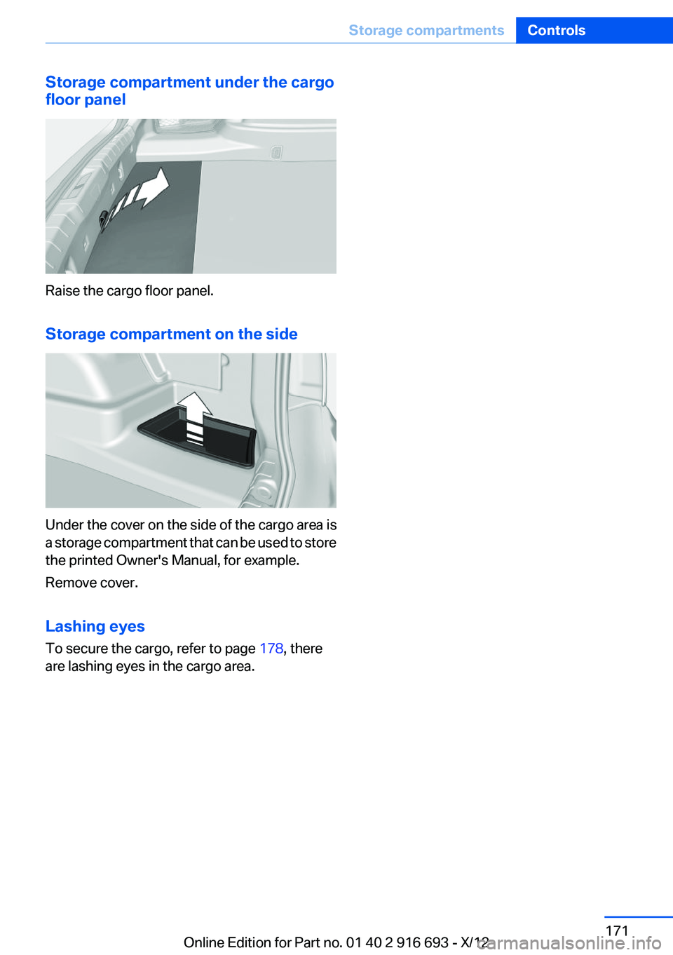
Storage compartment under the cargo
floor panel
Raise the cargo floor panel.
Storage compartment on the side
Under the cover on the side of the cargo area is
a storage compartment that can be used to store
the printed Owner's Manual, for example.
Remove cover.
Lashing eyes
To secure the cargo, refer to page 178, there
are lashing eyes in the cargo area.
Seite 171Storage compartmentsControls171
Online Edition for Part no. 01 40 2 916 693 - X/12
Page 176 of 243
Do not place additional floor mats over existing
mats or other objects.
Only use floor mats that have been approved for
the vehicle and can be properly fixed in place.
Ensure that the floor mats are securely fastened
again after they were removed for cleaning, for
example.◀
Driving in wet conditions
When roads are wet or there is heavy rain, briefly
exert gentle pressure on the brake pedal every
few miles.
Ensure that this action does not endanger other
road users.
The heat generated in this process helps dry the
brake discs and pads.
In this way braking efficiency will be available
when you need it.
Hills
Drive long or steep downhill gradients in the gear
in which the least braking is required. Otherwise,
the brake system may overheat, resulting in a
reduction in the brake system efficiency.
You can increase the engine's braking effect by
shifting down, going all the way to first gear, if
necessary.
Avoid load on the brakes
Avoid placing excessive load on the brake
system. Light but consistent brake pressure can
lead to high temperatures, brake wear and pos‐
sibly even brake failure.◀
Do not drive in neutral
Do not drive in neutral or with the engine
stopped, as doing so disables engine braking. In
addition, steering and brake assist is unavailable
with the engine stopped.◀
Brake disc corrosion
Corrosion on the brake discs and contamination
on the brake pads are furthered by:▷Low mileage.▷Extended periods when the vehicle is not
used at all.▷Infrequent use of the brakes.
Corrosion occurs when the minimum pressure
that must be exerted by the pads during brake
applications to clean the discs is not reached.
Should corrosion form on the brake discs, the
brakes will tend to respond with a pulsating ef‐
fect that generally cannot be corrected.
Condensation under the parked vehicle
When using the automatic climate control, con‐
densation water develops that exits underneath
the vehicle.
Traces of water under the vehicle like this are
normal.
Seite 176Driving tipsThings to remember when driving176
Online Edition for Part no. 01 40 2 916 693 - X/12